Documentation
This is the multi-page printable view of this section. Click here to print.
Documentation
- 1: Tanmatsu
- 2: I2C VFD (NE-HCS12SS59T-R1)
- 3: OpenBMC
- 3.1: ASRock Rack
- 3.1.1: ASRock Rack X570D4U
- 3.1.1.1: ASRock Rack X570D4U mainboard: pinout
- 3.1.1.2: ASRock Rack X570D4U mainboard: I2C busses
- 3.1.1.3: ASRock Rack X570D4U mainboard: GPIO
- 3.1.1.4: Programming SPI flash with an FT2232 breakout board
- 3.1.1.5: ASRock Rack X570D4U mainboard: temperature sensors
- 3.1.1.6: ASRock Rack X570D4U mainboard: fans
- 3.1.2: ASRock Rack PAUL
- 3.1.2.1: ASRock Rack PAUL: GPIO
- 4: Contributors guide
- 4.1: CLA
1 - Tanmatsu
The documentation for the Tanmatsu project has been moved to a separate Tanmatsu documentation website. This new website, licensed under terms of the CC-BY 4.0 license, allows users to submit changes. You can find the source code of the website on Github. Contributions are welcome!
2 - I2C VFD (NE-HCS12SS59T-R1)
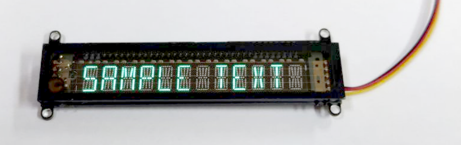
What is it?
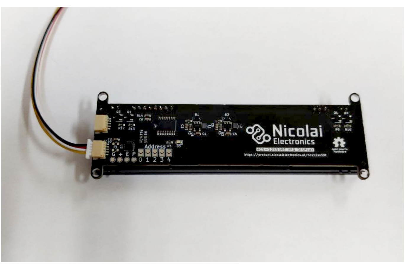
A Samsung HCS-12SS59T 12 character vacuum fluorescent display connected to a custom driver board which takes away all the difficulties of using such a display. The driver board does everything for you, from step-up voltage generation to having a microcontroller that translates between the display and an easy to use I2C interface.
Why did you make it?
I like weird and wonderful displays and this display deserves a spot in cool DIY projects. Unfortunately it is not exactly plug-and-play for use in Arduino, MicroPython or Raspberry pi projects.
What makes it special?
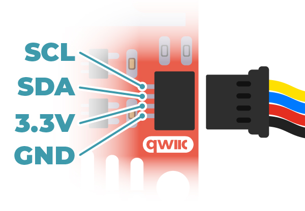
Everything is handled on-board, from generating the required voltages to handling the display control signals. All you have to do is hook up this module via I2C using the QWIIC / Stemma QT connectors on this board. There is two of them allowing for easy daisy chaining with more displays or other QWIIC/Stemma QT boards.
Sources
The hardware design files can be found in the hardware repository and the firmware can be found in the firmware repository.
How to use the device
The device can be connected to a microcontroller via the standardized QWIIC interface.
The device is compatible with a supply voltage of 3.3 volt. The I2C interface requires a working voltage of 3.3 volt as well.
I2C interface
The default I2C address is 0x10. The address can be changed by bridging the address jumpers on the board. This allows for modifying the I2C address in the range 0x10 up to 0x2F. Jumper 0 increases the address by 1, jumper 1 increases the address by 2, jumper 3 increases the address by 4 and jumper 4 increases the address by 8.
Register map
| Register | Name | Bit 7 | Bit 6 | Bit 5 | Bit 4 | Bit 3 | Bit 2 | Bit 1 | Bit 0 |
|---|---|---|---|---|---|---|---|---|---|
| 0 | System control | Reserved (0) | Reserved (0) | Reserved (0) | Reserved (0) | Reserved (0) | LED state | Test mode | Display enable |
| 1 | Display offset | Offset bit 7 | Offset bit 6 | Offset bit 5 | Offset bit 4 | Offset bit 3 | Offset bit 2 | Offset bit 1 | Offset bit 0 |
| 2 | Scroll length | Length bit 7 | Length bit 6 | Length bit 5 | Length bit 4 | Length bit 3 | Length bit 2 | Length bit 1 | Length bit 0 |
| 3 | Scroll mode | Reserved (0) | Reserved (0) | Reserved (0) | Loop enable | Mode bit 3 | Mode bit 2 | Mode bit 1 | Mode bit 0 |
| 4 | Scroll speed LO | Speed bit 7 | Speed bit 6 | Speed bit 5 | Speed bit 4 | Speed bit 3 | Speed bit 2 | Speed bit 1 | Speed bit 0 |
| 5 | Scroll speed HI | Speed bit 15 | Speed bit 14 | Speed bit 13 | Speed bit 12 | Speed bit 11 | Speed bit 10 | Speed bit 9 | Speed bit 8 |
| 6 | Filament current | Current bit 7 | Current bit 6 | Current bit 5 | Current bit 4 | Current bit 3 | Current bit 2 | Current bit 1 | Current bit 0 |
| 7 | Reserved (0) | Reserved (0) | Reserved (0) | Reserved (0) | Reserved (0) | Reserved (0) | Reserved (0) | Reserved (0) | Reserved (0) |
| 8 | Reserved (0) | Reserved (0) | Reserved (0) | Reserved (0) | Reserved (0) | Reserved (0) | Reserved (0) | Reserved (0) | Reserved (0) |
| 9 | Reserved (0) | Reserved (0) | Reserved (0) | Reserved (0) | Reserved (0) | Reserved (0) | Reserved (0) | Reserved (0) | Reserved (0) |
| 10 - 255 | Data (ASCII) | Reserved (0) | ASCII bit 6 | ASCII bit 5 | ASCII bit 4 | ASCII bit 3 | ASCII bit 2 | ASCII bit 1 | ASCII bit 0 |
Scrolling modes
0 = Scrolling disable
1 = Scroll left (increment display offset)
2 = Scroll right (decrement display offset)
Filament current
Note: filament current is only supported on firmware version 2, on firmware version 1 writing to this register will not do anything.
Default value is 110, lower is less current, higher is more current.
If set too high you will see the cathode wires glow slightly, this will reduce the lifespan of the display and thus we recommend to stick with the default value of 110 or lower.
When the display gets older you might need to increase the current slightly to keep the brightness level at an acceptable level, though it will take years of use before this is required.
Usage
Basic usage
At power on the display is automatically enabled. Writing ASCII text to registers 10 through 255 will make the text appear on the display.
To move the position in the buffer which is shown on the display you can write an offset to register 1 (display offset).
System control
To turn off the display write 0 to bit 0 of register 0, to turn on the display write a 1 to bit 0 of register 0. The LED can be controlled using bit 2 of register 0.
Scrolling
The automatic scrolling feature automatically updates the value of register 2 (display offset) to make the text shown on the display scroll without interaction by the bus master.
To enable automatic scrolling first write the maximum value the offset register should reach by setting the value of register 2 (scroll length). To stop scrolling once the last character of a string of text is shown on the rightmost position of the display set the value of this register to the length of the string minus 12 (the amount of characters the VFD can display).
Then write the speed at which you wish the characters to scroll into registers 4 and 5. This value is a 16-bit number representing the amount of milliseconds to wait before moving to the next character.
If scrolling was used before then resetting the current display offset to 0 makes sure the display starts scrolling from the beginning of the text.
To start scrolling write 1 to register 3. This will cause the text to scroll to the left automatically. Scrolling will stop once the scroll length value is reached. To automatically reset to the start of the string the loop function can be enabled by writing 17 (16, loop enable + 1, scroll left) to register 3.
For better readability adding 12 spaces to the front of the string to be scrolled is adviced, this makes the scrolling text start by scrolling in from the right into a blank screen.
Example Arduino sketch
The following Arduino sketch shows basic usage and how to use the built-in automatic scrolling features of the product.
// This example sketch may be freely used and considered in the public domain
// in countries where releasing code into the public domain is not possible
// this code may be used under the terms specified in the CC0 license
// https://creativecommons.org/public-domain/cc0/

#include <Wire.h>

#define VFD_REG_CTRL         0
#define VFD_REG_OFFSET       1
#define VFD_REG_SCROLL_LEN   2
#define VFD_REG_SCROLL_MODE  3
#define VFD_REG_SCROLL_SPEED 4
#define VFD_REG_DATA         10

#define VFD_SCROLL_DISABLE   0
#define VFD_SCROLL_LEFT      1
#define VFD_SCROLL_RIGHT     2

const int16_t I2C_ADDR = 0x10;

// Functions for reading and writing

void vfd_read_regs(uint8_t reg, uint8_t* val, uint8_t len) {
  Wire.beginTransmission(I2C_ADDR);
  Wire.write(reg);
  Wire.endTransmission(false);
  Wire.requestFrom((uint8_t) I2C_ADDR, (uint8_t) len);
  for (uint8_t index = 0; index < len; index++) {
    val[index] = Wire.read();
  }
  Wire.endTransmission();
}

void vfd_read_reg(uint8_t reg, uint8_t* val) {
  vfd_read_regs(reg, val, 1);
}

void vfd_write_regs(uint8_t reg, uint8_t* val, uint8_t len) {
  Serial.print("I2C write to register " + String(reg) + ": ");
  Wire.beginTransmission(I2C_ADDR);
  Wire.write(reg);
  for (uint8_t index = 0; index < len; index++) {
    Serial.print(String(val[index], HEX) + ", ");
    Wire.write(val[index]);
  }
  Serial.println();
  Wire.endTransmission();
}

void vfd_write_reg(uint8_t reg, uint8_t val) {
  vfd_write_regs(reg, &val, 1);
}

// Functions for using the control register

void vfd_control_led(bool state) {
  uint8_t val = 0;
  vfd_read_reg(VFD_REG_CTRL, &val);
  Serial.println("LED, READ  " + String(val, HEX));
  val &= ~(1 << 2); // Turn off the LED
  if (state) {
    val |= (1 << 2); // Turn on the LED
  }
  Serial.println("LED, WRITE " + String(val, HEX));
  vfd_write_reg(VFD_REG_CTRL, val);
}

void vfd_control_test(bool state) {
  uint8_t val = 0;
  vfd_read_reg(VFD_REG_CTRL, &val);
  val &= ~(1 << 1); // Turn off the test mode
  if (state) {
    val |= (1 << 1); // Turn on the test mode
  }
  vfd_write_reg(VFD_REG_CTRL, val);
}

void vfd_control_enable(bool state) {
  uint8_t val = 0;
  vfd_read_reg(VFD_REG_CTRL, &val);
  val &= ~(1 << 0); // Turn off the VFD
  if (state) {
    val |= (1 << 0); // Turn on the VFD
  }
  vfd_write_reg(VFD_REG_CTRL, val);
}

void vfd_control(bool enable, bool test, bool led) {
  uint8_t val = 0;
  if (enable) {
    val |= (1 << 0);
  }
  if (test) {
    val |= (1 << 1);
  }
  if (led) {
    val |= (1 << 2);
  }
  vfd_write_reg(VFD_REG_CTRL, val);
}

// Functions for using the scroll features

void vfd_set_offset(uint8_t offset) {
  vfd_write_reg(VFD_REG_OFFSET, offset);
}

void vfd_set_scroll_length(uint8_t len) {
  vfd_write_reg(VFD_REG_SCROLL_LEN, len);
}

void vfd_set_scroll_mode(uint8_t scroll_mode, bool scroll_loop) {
  uint8_t val = scroll_mode & 0x0F;
  if (scroll_loop) {
    val |= (1 << 4);
  }
  vfd_write_reg(VFD_REG_SCROLL_MODE, val);
}

void vfd_set_scroll_speed(uint16_t scroll_speed) {
  uint8_t values[2];
  values[0] = (scroll_speed) & 0xFF;
  values[1] = (scroll_speed >> 8) & 0xFF;
  vfd_write_regs(VFD_REG_SCROLL_SPEED, values, sizeof(uint16_t));
}

// Functions for using the text buffer

void vfd_write_text(String text) {
  // This function writes an ASCII string into
  // register 10 to 255

  const size_t max_len = 245; // can store text in registers 10 to 255
  size_t len = text.length();

  if (len > max_len) {
    // Silently limit the length of the string
    len = max_len;
  }

  Wire.beginTransmission(I2C_ADDR);
  Wire.write(VFD_REG_DATA);
  for (size_t index = 0; index < len; index++) {
    Wire.write(text[index]);
  }
  Wire.endTransmission();
}

// Functions for Arduino program

void setup() {
  Serial.begin(115200);

  Serial.println("Initialize I2C bus");
  Wire.begin(); // Initialize the I2C bus

  // Configure the display and show a message
  Serial.println("Configure the display and show a message");
  vfd_set_scroll_mode(VFD_SCROLL_DISABLE, false); // Disable scrolling
  vfd_set_offset(0); // Move to beginning of text buffer
  vfd_write_text("Hello world ");
  vfd_control(true, false, true); // Turn on VFD and LED
  delay(1000); // Wait a bit

  Serial.println("Demonstrate scrolling");
  String text = "            The quick brown fox jumps over the lazy dog 0123456789 !@$%^&*()-_=+";
  vfd_write_text(text);
  vfd_set_scroll_length(text.length() - 12); // Scroll until the last character of the string is on the most right character of the display
  vfd_set_scroll_speed(100); // Scroll one character every 100ms
  vfd_set_scroll_mode(VFD_SCROLL_LEFT, false); // Scroll left then stop
  vfd_control_led(false);
  delay(10000);

  vfd_set_scroll_mode(VFD_SCROLL_RIGHT, false); // Scroll right then stop
  vfd_control_led(true); // Turn on LED
  delay(10000);

  vfd_set_scroll_mode(VFD_SCROLL_LEFT, true); // Scroll left then loop
  vfd_control_led(false); // Turn off LED
  delay(20000);

  vfd_set_scroll_mode(VFD_SCROLL_DISABLE, false); // Disable scrolling
  vfd_write_text("            "); // Clear screen
  vfd_set_offset(0); // Move to beginning of text buffer
  vfd_control_led(true); // Turn on LED

  Serial.println("Starting counter loop");
}

uint32_t counter = 0;
void loop() {
  // Count as fast as we can
  vfd_write_text(String(counter));
  counter++;
}
What does it look like?
3 - OpenBMC
OpenBMC is an open source Linux distribution for Baseboard Management Controllers. Nicolai Electronics works on enabling more boards to run this open source firmware instead of manufacturer provided proprietary solutions. More information can be found on the board specific pages.
3.1 - ASRock Rack
ASRock Rack is a hardware manufacturer which has produced multiple mainboards and devices which should be capable of running OpenBMC. More information on the boards Nicolai Electronics is working can be found on the board specific pages.
3.1.1 - ASRock Rack X570D4U
Project status: in progress
The ASRock Rack X570D4U series of mainboards consists of three mainboards with an AMD X570 chipset and AM4 socket. ASRock Rack sells the board in three versions: a cost reduced version without a 10Gbit NIC (X570D4U), a version with an Intel 10Gbit NIC (X570D4U-2L2T) and a version with a Broadcom 10Gbit NIC (X570D4U-2L2T/BCM). These boards contain an Aspeed AST2500 BMC chip. A Baseboard Management Controller (BMC) is a small computer built into the motherboard that allows for out-of-band management. It allows for remote power control, KVM (remote keyboard, video and mouse) control, virtual media insertion and much more.
| Property | Value | Part |
|---|---|---|
| Processor | ARM1176JZS (ARMv6) @ 800MHz | AST2500 SoC |
| RAM | 512MB DDR4 | K4A4G165WE |
| Storage | 64MB SPI flash | MX25L51245G |
These parts make for quite a powerful system, unfortunately the operating system shipped by ASRock Rack is proprietary and dos not allow for easy modification. To allow for a more secure, transparent and customizable experience we are working on adding support for this mainboard to the mainline Linux kernel and the OpenBMC Linux distribution for BMCs.
Official documentation is provided in ASRock Racks manual for these mainboards. Not a all headers and connectors are described in this manual. The pinout of the undocumented connectors and headers can be found on the pinout page.
The BMC has a programming header, a debug serial port, I2C busses and GPIOs.
Project status
Enabling the use of the mainline Linux kernel and OpenBMC on this hardware is an ongoing effort. An initial port of OpenBMC missing most board specific features can be found here.
3.1.1.1 - ASRock Rack X570D4U mainboard: pinout
This page describes the undocumented headers and connectors on the ASRock X570D4U mainboard. The official manual for this mainboard describes most other connectors and headers.
BMC debug header
This header labeled BMC_DEBUG1 provides access to the debug serial port of the AST2500 SoC (UART 5). The UART works with 3.3v level signals and provides a 3.3v output and can be found on the bottom left of the mainboard.
Using this port you can access the U-Boot command prompt, the Linux bootlog and a shell.
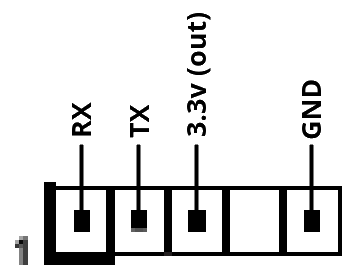
BMC programming header
This header labeled BMC_PH1 provides access to the MX25L51245G 64MB flash chip containing the BMC firmware. Using an exernal SPI flash programmer this port allows for unbricking and easy reflashing of the BMC firmware during development.
This interface uses 3.3v level signals. Connecting the BMC RESET# pin to GND disables the AST2500, allowing an exernal programmer to reprogram the flash chip without interference from the SoC.
Manufacturing mode header
This header labeled MFG1 is connected to GPIO H4 of the AST2500 SoC. With the official firmware installed shorting this jumper makes the BMC boot into a special debug mode, dropping to a root shell on the BMC_DEBUG1 port. When running OpenBMC this GPIO is available for custom applications.
Chassis identification
These three headers labeled CHASSIS_ID1, CHASSIS_ID2 and CHASSIS_ID3 are connected to GPIO G1, G2 and G3 of the AST2500 SoC for ID1, ID2 and ID3 respectively. On production boards these headers appear to not have been installed, but they are functional. When running OpenBMC these GPIOs are available for custom applications.
3.1.1.2 - ASRock Rack X570D4U mainboard: I2C busses
This page describes the I2C busses and connected on-board devices on the ASRock X570D4U mainboard.
I2C bus 0
This bus is connected to the AUX_PANEL1 connector. SMBus alert for this bus is connected to GPIO 52 (G4) named input-aux-smb-alert-n.
| Device | Address | Available when host is off | Description |
|---|---|---|---|
| AUX panel SMBus header (AUX_PANEL1) | — | Yes | Standard 2.54mm header, pinout is in manual |
I2C bus 1
This bus is used for controlling on-board devices that are used when the host is on.
| Device | Address | Available when host is off | Description |
|---|---|---|---|
| PCA9557 IO expander | 0x1C | No | Controls the FAN fault LEDs |
| Unknown device | 0x1D | No | Unknown |
| Nuvoton NCT6796D-R SuperIO | 0x2D | No | Host temperature monitoring interface (SuperIO) |
| Nuvoton W83773G | 0x4C | Yes | Temperature monitoring interface for 10G NIC (Not installed on base model X570D4U boards) |
PCA9557 IO expander
| Pin | Direction | Function |
|---|---|---|
| 0 | Output | Fault LED for FAN 4 |
| 1 | Output | Fault LED for FAN 5 |
| 2 | Output | Fault LED for FAN 1 |
| 3 | Output | Unknown / not connected |
| 4 | Output | Fault LED for FAN 2 |
| 5 | Output | Fault LED for FAN 3 |
| 6 | Output | Fault LED for FAN 6 |
| 7 | Output | Unknown / not connected |
Nuvoton NCT6796D-R SuperIO
This chip can read the CPU and chipset temperatures. It should be possible to use the newly added nct6775-i2c driver to use this device.
Using the NCT6775-I2C driver
The OpenBMC port for the X570D4U already includes the nct6775-i2c driver in it’s kernel, but as the SuperIO device only appears on the bus when the host system is powered on the driver needs to be loaded in and unloaded based on power state changes. This has not been implemented yet.
The driver can be manually loaded in using the following command:
echo "nct6775 0x2d" > /sys/bus/i2c/devices/i2c-1/new_device
If the driver was loaded correctly then you should now be able to find a folder called hwmon in the device folder /sys/bus/i2c/devices/i2c-1/1-002d. This folder will contain a symlink to the hwmon interface for the SuperIO chip. If the folder is missing then your kernel does not include the nct6775-i2c driver.
Directly accessing and reading the temperature registers
Alternatively the temperatures can be read using this shell script, for which no kernel driver is required:
#!/bin/bash
i2cset -y 1 0x2d 0x4e 0x04
while :
do
    TSI0INT=$((16#$(i2cget -y 1 0x2d 0x09 | cut -f2 -dx)))
    TSI0FRC=$(($((16#$(i2cget -y 1 0x2d 0x0a | cut -f2 -dx)))>>5))
    TSI1INT=$((16#$(i2cget -y 1 0x2d 0x0b | cut -f2 -dx)))
    TSI1FRC=$(($((16#$(i2cget -y 1 0x2d 0x0c | cut -f2 -dx)))>>5))
    echo "TSI0_TEMP: $TSI0INT.$TSI0FRC °C / TSI1_TEMP: $TSI1INT.$TSI1FRC °C"
    sleep 0.5
done
Nuvoton W83773G
This device is available on the versions of the X570D4U which include a 10Gbit network adapter. It monitors the temperature of the 10Gbit NIC.
cat /sys/class/hwmon/hwmon0/temp2_input
I2C bus 2
This bus is used for connecting to exernal power supplies with SMBus monitoring support using the PSU_SMB1 connector. SMBus alert for this bus is connected to GPIO 54 (G6) named input-psu-smb-alert-n.
| Device | Address | Available when host is off | Description |
|---|---|---|---|
| PSU SMBus header (PSU_SMB1) | — | Yes | MOLEX 70543-0003 connector, pinout is in manual |
I2C bus 3
This bus has an unknown purpose.
| Device | Address | Available when host is off | Description |
|---|---|---|---|
| Unknown device | 0x13 | Yes | Unknown |
| Unknown device | 0x14 | No | Unknown |
| Unknown device | 0x15 | No | Unknown |
I2C bus 4
This bus is used to connect to expansion cards inserted into the PCI-Express slots of the mainboard.
| Device | Address | Available when host is off | Description |
|---|---|---|---|
| NXP PCA9545A I2C bus switch | 0x70 | Yes | Bus multiplexer for switching between PCIe slots |
NXP PCA9545A I2C bus switch
| Bus | Port |
|---|---|
| 0 | PCI express 16x slot |
| 1 | PCI express 8x slot |
| 2 | Unknown |
| 3 | PCI express 1x slot |
I2C bus 5
This bus is connected to the BMC_SMB_1 connector. The BMC_PRESENT_1_N signal on the BMC_SMB_1 connector is connected to GPIO 132 (Q4) named input-bmc-smb-present-n.
| Device | Address | Available when host is off | Description |
|---|---|---|---|
| BMC SMbus header (BMC_SMB_1) | — | Yes | Unknown connector, pinout is in manual (might be MOLEX 353620550) |
I2C bus 7
This bus is used for connecting to the FRU EEPROM and the RAM DIMMs.
| Device | Address | Available when host is off | Description |
|---|---|---|---|
| RAM DIMM A1 temperature sensor | 0x1A | No | |
| RAM DIMM A2 temperature sensor | ???? | No | Not tested yet |
| RAM DIMM B1 temperature sensor | 0x1B | No | |
| RAM DIMM B2 temperature sensor | ???? | No | Not tested yet |
| Unknown device | 0x30 | No | Unknown |
| Unknown device | 0x35 | No | Unknown |
| Unknown device | 0x36 | No | Unknown |
| RAM DIMM A1 SPD EEPROM | 0x52 | No | |
| RAM DIMM A2 SPD EEPROM | ???? | No | Not tested yet |
| RAM DIMM B1 SPD EEPROM | 0x53 | No | |
| RAM DIMM B2 SPD EEPROM | ???? | No | Not tested yet |
| FRU EEPROM | 0x57 | Yes |
I2C bus 8
This bus is connected to the IPMB_1 connector.
| Device | Address | Available when host is off | Description |
|---|---|---|---|
| IPMI SMbus header (IPMB_1) | — | Yes | MOLEX 22035045 connector, pinout is in manual |
3.1.1.3 - ASRock Rack X570D4U mainboard: GPIO
This page describes the GPIOs of the ASPEED AST2500 BMC on the ASRock X570D4U mainboard.
| # | ID | Power domain | Peripheral | Type | Name | Description |
|---|---|---|---|---|---|---|
| 0 | A0 | PV33D | GPIO | Input | input-locatorled-n | State of the locator LED (active low) |
| 1 | A1 | PV33D | ||||
| 2 | A2 | PV33D | ||||
| 3 | A3 | PV33D | ||||
| 4 | A4 | I2C | I2C bus 8 clock (IPMB SMBus) | |||
| 5 | A5 | I2C | I2C bus 8 data (IPMB SMBus) | |||
| 6 | A6 | |||||
| 7 | A7 | |||||
| 8 | B0 | LPVDD | GPIO | Input | input-bios-post-cmplt-n | BIOS has completed POST stage (active low) |
| 9 | B1 | LPVDD | (Changes on host boot) | |||
| 10 | B2 | LPVDD | (Changes on host boot) | |||
| 11 | B3 | LPVDD | ||||
| 12 | B4 | LPVDD | (Changes on host boot) | |||
| 13 | B5 | LPVDD | ||||
| 14 | B6 | LPVDD | ||||
| 15 | B7 | LPVDD | (Changes on host boot) | |||
| 16 | C0 | (I2C bus 9 clock) | ||||
| 17 | C1 | (I2C bus 9 data) | ||||
| 18 | C2 | (I2C bus 10 clock) | ||||
| 19 | C3 | (I2C bus 10 data) | ||||
| 20 | C4 | (I2C bus 11 clock) | ||||
| 21 | C5 | (I2C bus 11 data) | ||||
| 22 | C6 | GPIO | Output open drain | control-locatorbutton-n | Pull low to emulate identification button press | |
| 23 | C7 | |||||
| 24 | D0 | GPIO | Input | button-power-n | State of the power button (active low) | |
| 25 | D1 | GPIO | Output open drain | control-power-n | Pull low to emulate power button press | |
| 26 | D2 | GPIO | Input | button-reset-n | State of the reset button (active low) | |
| 27 | D3 | GPIO | Output open drain | control-reset-n | Pull low to emulate reset button press | |
| 28 | D4 | |||||
| 29 | D5 | |||||
| 30 | D6 | |||||
| 31 | D7 | |||||
| 32 | E0 | (UART3 CTS) | ||||
| 33 | E1 | (UART3 DCD) | ||||
| 34 | E2 | (UART3 DSR) | ||||
| 35 | E3 | (UART3 RING) | ||||
| 36 | E4 | (UART3 DTR) | ||||
| 37 | E5 | (UART3 RTS) | ||||
| 38 | E6 | (UART3 TX) | ||||
| 39 | E7 | (UART3 RX) | ||||
| 40 | F0 | (UART4 CTS, LPC HOST BIT 0) | ||||
| 41 | F1 | (UART4 DCD, LPC HOST BIT 1) | ||||
| 42 | F2 | (UART4 DSR, LPC HOST BIT 2) | ||||
| 43 | F3 | (UART4 RING, LPC HOST BIT 3) | ||||
| 44 | F4 | (UART4 DTR, LPC HOST CLOCK IO) | ||||
| 45 | F5 | (UART4 RTS, LPC HOST FRAME#) | ||||
| 46 | F6 | (UART4 TX, LPC HOST SERIRQ#, maybe BMC_PCH_SCI_LPC) | ||||
| 47 | F7 | (UART4 RX, LPC HOST RESET IO, maybe BMC_NCSI_MUX_STL) | ||||
| 48 | G0 | GPIO | Output | output-hwm-vbat-enable | Pull high to connect the RTC battery to ADC9 | |
| 49 | G1 | GPIO | Input | input-id0-n | Pulled low when jumper ID0 is closed | |
| 50 | G2 | GPIO | Input | input-id1-n | Pulled low when jumper ID1 is closed | |
| 51 | G3 | GPIO | Input | input-id2-n | Pulled low when jumper ID2 is closed | |
| 52 | G4 | GPIO | Input | input-aux-smb-alert-n | SMBus alert for I2C bus 0 (AUX_PANEL1) | |
| 53 | G5 | |||||
| 54 | G6 | GPIO | Input | input-psu-smb-alert-n | SMBus alert for I2C bus 2 (PSU_SMB1) | |
| 55 | G7 | |||||
| 56 | H0 | |||||
| 57 | H1 | |||||
| 58 | H2 | |||||
| 59 | H3 | |||||
| 60 | H4 | GPIO | Input | input-mfg-mode-n | Pulled low when jumper MFG1 is closed | |
| 61 | H5 | |||||
| 62 | H6 | GPIO | Output | led-heartbeat-n | Controls the green heartbeat LED on the board (active low) | |
| 63 | H7 | GPIO | Input | input-case-open-n | High while case open button is pressed, low when released | |
| 64 | I0 | (SYSCS#) | ||||
| 65 | I1 | (SYSCK) | ||||
| 66 | I2 | (SYSMOSI) | ||||
| 67 | I3 | (SYSMISO) | ||||
| 68 | I4 | (SPI1CS0# / VBCS#) | ||||
| 69 | I5 | (SPI1CK / VBCK) | ||||
| 70 | I6 | (SPI1MOSI / VBMOSI) | ||||
| 71 | I7 | (SPI1MISO / VBMISO) | ||||
| 72 | J0 | GPIO | Output | output-bmc-ready-n | Signals to the host that the BMC is ready (active low) | |
| 73 | J1 | (guess based on other asrock boards: BMC_PCH_BIOS_CS_N) | ||||
| 74 | J2 | |||||
| 75 | J3 | |||||
| 76 | J4 | VGA | VGA horizontal sync | |||
| 77 | J5 | VGA | VGA vertical sync | |||
| 78 | J6 | VGA | VGA DDC clock | |||
| 79 | J7 | VGA | VGA DDC data | |||
| 80 | K0 | I2C | I2C bus 4 clock (PCI Express SMBus) | |||
| 81 | K1 | I2C | I2C bus 4 data (PCI Express SMBus) | |||
| 82 | K2 | I2C | I2C bus 5 clock (BMC SMBus) | |||
| 83 | K3 | I2C | I2C bus 5 data (BMC SMBus) | |||
| 84 | K4 | (I2C bus 6 clock) | ||||
| 85 | K5 | (I2C bus 6 data) | ||||
| 86 | K6 | I2C | I2C bus 7 clock (FRU and SPD EEPROM SMBus) | |||
| 87 | K7 | I2C | I2C bus 7 data (FRU and SPD EEPROM SMBus) | |||
| 88 | L0 | (UART1 CTS) | ||||
| 89 | L1 | (UART1 DCD) | ||||
| 90 | L2 | (UART1 DSR) | ||||
| 91 | L3 | (UART1 RING) | ||||
| 92 | L4 | (UART1 DTR) | ||||
| 93 | L5 | (UART1 RTS) | ||||
| 94 | L6 | (UART1 TX) | ||||
| 95 | L7 | (UART1 RX) | ||||
| 96 | M0 | (UART2 CTS) | ||||
| 97 | M1 | (UART2 DCD) | ||||
| 98 | M2 | (UART2 DSR) | ||||
| 99 | M3 | (UART2 RING) | ||||
| 100 | M4 | (UART2 DTR) | ||||
| 101 | M5 | (UART2 RTS) | ||||
| 102 | M6 | (UART2 TX) | ||||
| 103 | M7 | (UART2 RX) | ||||
| 104 | N0 | PWM | FAN1 PWM output | |||
| 105 | N1 | PWM | FAN2 PWM output | |||
| 106 | N2 | PWM | FAN3 PWM output | |||
| 107 | N3 | PWM | FAN4 PWM output | |||
| 108 | N4 | PWM | FAN6 PWM output | |||
| 109 | N5 | PWM | FAN5 PWM output | |||
| 110 | N6 | |||||
| 111 | N7 | |||||
| 112 | O0 | Tachometer | FAN1 tachometer input | |||
| 113 | O1 | Tachometer | FAN2 tachometer input | |||
| 114 | O2 | Tachometer | FAN3 tachometer input | |||
| 115 | O3 | Tachometer | FAN4 tachometer input 1 | |||
| 116 | O4 | Tachometer | FAN5 tachometer input 1 | |||
| 117 | O5 | Tachometer | FAN6 tachometer input 1 | |||
| 118 | O6 | |||||
| 119 | O7 | |||||
| 120 | P0 | |||||
| 121 | P1 | |||||
| 122 | P2 | |||||
| 123 | P3 | Tachometer | FAN4 tachometer input 2 | |||
| 124 | P4 | Tachometer | FAN5 tachometer input 2 | |||
| 125 | P5 | Tachometer | FAN6 tachometer input 2 | |||
| 126 | P6 | |||||
| 127 | P7 | |||||
| 128 | Q0 | I2C | I2C bus 2 clock (PSU_SMB1) | |||
| 129 | Q1 | I2C | I2C bus 2 data (PSU_SMB1) | |||
| 130 | Q2 | I2C | I2C bus 3 clock | |||
| 131 | Q3 | I2C | I2C bus 3 data | |||
| 132 | Q4 | GPIO | Input | input-bmc-smb-present-n | BMC present input (BMC_SMB_1) | |
| 133 | Q5 | |||||
| 134 | Q6 | PV33D | ||||
| 135 | Q7 | PV33D | GPIO | Input | input-pcie-wake-n | Pulled low when a PCI Express card asserts WAKE# |
| 136 | R0 | |||||
| 137 | R1 | |||||
| 138 | R2 | (SPI2CS0#) | ||||
| 139 | R3 | (SPI2CK) | ||||
| 140 | R4 | (SPI2MOSI) | ||||
| 141 | R5 | (SPI2MISO) | ||||
| 142 | R6 | RGMII | MDC1 | |||
| 143 | R7 | RGMII | MDIO1 | |||
| 144 | S0 | PV33D | GPIO | Input | input-bmc-pchhot-n | Needs verification |
| 145 | S1 | PV33D | ||||
| 146 | S2 | PV33D | ||||
| 147 | S3 | PV33D | ||||
| 148 | S4 | PV33D | ||||
| 149 | S5 | PV33D | ||||
| 150 | S6 | PV33D | ||||
| 151 | S7 | PV33D | ||||
| 152 | T0 | RGMII | Dedicated LAN port: TXCK | |||
| 153 | T1 | RGMII | Dedicated LAN port: TXCL | |||
| 154 | T2 | RGMII | Dedicated LAN port: TXD0 | |||
| 155 | T3 | RGMII | Dedicated LAN port: TXD1 | |||
| 156 | T4 | RGMII | Dedicated LAN port: TXD2 | |||
| 157 | T5 | RGMII | Dedicated LAN port: TXD3 | |||
| 158 | T6 | RMII | NC-SI: RCLKO | |||
| 159 | T7 | RMII | NC-SI: TXEN | |||
| 160 | U0 | RMII | NC-SI: TXD0 | |||
| 161 | U1 | RMII | NC-SI: TXD1 | |||
| 162 | U2 | |||||
| 163 | U3 | |||||
| 164 | U4 | RGMII | Dedicated LAN port: RXCK | |||
| 165 | U5 | RGMII | Dedicated LAN port: RXCTL | |||
| 166 | U6 | RGMII | Dedicated LAN port: RXD0 | |||
| 167 | U7 | RGMII | Dedicated LAN port: RXD1 | |||
| 168 | V0 | RGMII | Dedicated LAN port: RXD2 | |||
| 169 | V1 | RGMII | Dedicated LAN port: RXD3 | |||
| 170 | V2 | RMII | NC-SI: CLKI | |||
| 171 | V3 | |||||
| 172 | V4 | RMII | NC-SI: RXD0 | |||
| 173 | V5 | RMII | NC-SI: RXD1 | |||
| 174 | V6 | RMII | NC-SI: CRSDV | |||
| 175 | V7 | RMII | NC-SI: RXER | |||
| 176 | W0 | ADC | Analog input representing 3VSB | |||
| 177 | W1 | ADC | Analog input representing 5VSB | |||
| 178 | W2 | ADC | Analog input representing VCPU | |||
| 179 | W3 | ADC | Analog input representing VSOC | |||
| 180 | W4 | ADC | Analog input representing VCCM | |||
| 181 | W5 | ADC | Analog input representing APU VDDP | |||
| 182 | W6 | ADC | Analog input representing PM VDD CLDO | |||
| 183 | W7 | ADC | Analog input representing PM VDDCR S5 | |||
| 184 | X0 | ADC | Analog input representing PM VDDCR | |||
| 185 | X1 | ADC | Analog input representing RTC battery voltage | |||
| 186 | X2 | ADC | Analog input representing 3V | |||
| 187 | X3 | ADC | Analog input representing 5V | |||
| 188 | X4 | ADC | Analog input representing 12V | |||
| 189 | X5 | (ADC) | ||||
| 190 | X6 | (ADC) | ||||
| 191 | X7 | (ADC) | ||||
| 192 | Y0 | PV33D | GPIO | Input | input-sleep-s3-n | Rising edge when host starts, not verified |
| 193 | Y1 | PV33D | GPIO | Input | input-sleep-s5-n | Rising edge when host starts, not verified |
| 194 | Y2 | PV33D | ||||
| 195 | Y3 | PV33D | ||||
| 196 | Y4 | I2C | I2C bus 0 clock (AUX_PANEL1) | |||
| 197 | Y5 | I2C | I2C bus 0 data (AUX_PANEL1) | |||
| 198 | Y6 | I2C | I2C bus 1 clock (SuperIO and thermal sensor) | |||
| 199 | Y7 | I2C | I2C bus 1 data (SuperIO and thermal sensor) | |||
| 200 | Z0 | PV33D | ||||
| 201 | Z1 | PV33D | ||||
| 202 | Z2 | PV33D | GPIO | Output | led-fault-n | |
| 203 | Z3 | PV33D | GPIO | Output | output-bmc-throttle-n | Needs verification |
| 204 | Z4 | PV33D | ||||
| 205 | Z5 | PV33D | ||||
| 206 | Z6 | PV33D | ||||
| 207 | Z7 | PV33D | ||||
| 208 | AA0 | PV33D | GPIO | Input | input-cpu1-thermtrip-latch-n | |
| 209 | AA1 | PV33D | ||||
| 210 | AA2 | PV33D | GPIO | Input | input-cpu1-prochot-n | |
| 211 | AA3 | PV33D | ||||
| 212 | AA4 | PV33D | ||||
| 213 | AA5 | PV33D | ||||
| 214 | AA6 | PV33D | ||||
| 215 | AA7 | PV33D | ||||
| 216 | AB0 | PV33D | ||||
| 217 | AB1 | PV33D | GPIO | Input | input-power-good | Rising edge when host starts, not verified |
| 218 | AB2 | PV33D | ||||
| 219 | AB3 | PV33D | ||||
| 220 | — | |||||
| 221 | — | |||||
| 222 | — | |||||
| 223 | — | |||||
| 224 | AC0 | LPC | LAD0 | |||
| 225 | AC1 | LPC | LAD1 | |||
| 226 | AC2 | LPC | LAD2 | |||
| 227 | AC3 | LPC | LAD3 | |||
| 228 | AC4 | LPC | Clock | |||
| 229 | AC5 | LPC | LFRAME | |||
| 230 | AC6 | LPC | IRQ | |||
| 231 | AC7 | LPC | Reset |
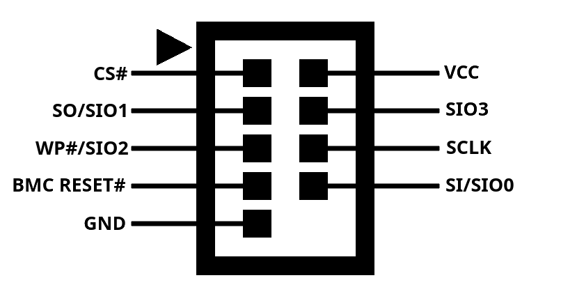
3.1.1.4 - Programming SPI flash with an FT2232 breakout board
Connection diagram
| Pin on Mainboard | Function SPI | Function QSPI | Pin on FTDI |
|---|---|---|---|
| CS# | Chip select | Chip select | ADBUS 3 |
| VCC | 3.3v output | 3.3v output | Not connected |
| SO/SIO1 | Data output | Data bit 1 | ADBUS 2 |
| SIO3 | Unused | Data bit 3 | Not connected |
| WP#/SIO2 | Write protect | Data bit 2 | Not connected |
| SCLK | Clock | Clock | ADBUS 0 |
| BMC RESET# | Reset | Reset | Ground |
| SI/SIO0 | Data input | Data bit 0 | ADBUS 1 |
| GND | Ground | Ground | Ground |
3.1.1.5 - ASRock Rack X570D4U mainboard: temperature sensors
This page describes the temperature sensors on the X570D4U.
Nuvoton NCT6796D-R SuperIO
This device can be accessed via I2C bus 1 at address 0x2D.
| Input | Valid | Description |
|---|---|---|
| SYSTIN | Yes | Close to SuperIO chip, could be MB temperature |
| CPUTIN | No | |
| AUXTIN0 | No | |
| AUXTIN1 | Yes | Close to SuperIO chip, could be MB temperature |
| AUXTIN2 | Yes | Bottom left corner of the board, Card side temperature |
| AUXTIN3 | No | |
| AUXTIN4 | No | |
| TSI0_TEMP | Yes | CPU temperature |
| TSI1_TEMP | Yes | Chipset temperature |
Nuvoton W83773G
This device can be accessed via I2C bus 1 at address 0x4C.
| Input | Valid | Description |
|---|---|---|
| temp1_input | Yes | Inside of the W83773G, located close to the 10Gbit NIC |
| temp2_input | Yes | Cconnected to a temperature diode in or close to the 10Gbit NIC |
| temp3_input | No |
3.1.1.6 - ASRock Rack X570D4U mainboard: fans
This page describes the fan connectors on the X570D4U.
Fan connectors
| Connector | PWM | Tacho 1 | Tacho 2 |
|---|---|---|---|
| 1 | 1 | 1 | - |
| 2 | 2 | 2 | - |
| 3 | 3 | 3 | - |
| 4 | 4 | 4 | 12 |
| 5 | 6 | 5 | 13 |
| 6 | 5 | 6 | 14 |
Fan 1-3 connector pinout
| Pin | Function | Asrock label |
|---|---|---|
| 1 | Ground | GND |
| 2 | Power | FAN_VOLTAGE |
| 3 | Tacho 1 | FAN_SPEED |
| 4 | PWM | FAN_SPEED_CONTROL |
Fan 4-6 connector pinout
| Pin | Function | Asrock label |
|---|---|---|
| 1 | Ground | GND |
| 2 | Power | FAN_VOLTAGE |
| 3 | Tacho 1 | FAN_SPEED |
| 4 | PWM | FAN_SPEED_CONTROL |
| 5 | Tacho 2 | SENSOR |
| 6 | - | NC |
3.1.2 - ASRock Rack PAUL
Project status: in progress
The ASRock Rack PAUL is a PCI-express add-in card for servers and workstations containing an Aspeed AST2500 BMC chip. A Baseboard Management Controller (BMC) is a small computer that allows for out-of-band management. It allows for remote power control, KVM (remote keyboard, video and mouse) control, virtual media insertion and much more.
| Property | Value | Part |
|---|---|---|
| Processor | ARM1176JZS (ARMv6) @ 800MHz | AST2500 SoC |
| RAM | 512MB DDR4 | K4A4G165WE-BCRC |
| Storage | 3x 32MB SPI flash | MX25L25645G |
These parts make for quite a powerful system, unfortunately the operating system shipped by ASRock Rack is proprietary and dos not allow for easy modification. To allow for a more secure, transparent and customizable experience we are working on adding support for this mainboard to the mainline Linux kernel and the OpenBMC Linux distribution for BMCs.
Official documentation is provided in ASRock Racks manual.
3.1.2.1 - ASRock Rack PAUL: GPIO
This page describes the GPIOs of the ASPEED AST2500 BMC on the ASRock Rack Paul card.
| # | ID | Power domain | Peripheral | Type | Name | Description | Verified |
|---|---|---|---|---|---|---|---|
| 0 | A0 | PV33D | |||||
| 1 | A1 | PV33D | |||||
| 2 | A2 | PV33D | GPIO | Input | input-nmi | NMI input on pinheader | Yes |
| 3 | A3 | PV33D | |||||
| 4 | A4 | I2C | I2C bus 8 clock (IPMB_1) | Yes | |||
| 5 | A5 | I2C | I2C bus 8 data (IPMB_1) | Yes | |||
| 6 | A6 | ||||||
| 7 | A7 | ||||||
| 8 | B0 | LPVDD | |||||
| 9 | B1 | LPVDD | |||||
| 10 | B2 | LPVDD | |||||
| 11 | B3 | LPVDD | |||||
| 12 | B4 | LPVDD | |||||
| 13 | B5 | LPVDD | |||||
| 14 | B6 | LPVDD | |||||
| 15 | B7 | LPVDD | |||||
| 16 | C0 | SD card | SD card 1: CLK | Yes | |||
| 17 | C1 | SD card | SD card 1: CMD | Yes | |||
| 18 | C2 | SD card | SD card 1: DAT0 | Yes | |||
| 19 | C3 | SD card | SD card 1: DAT1 | Yes | |||
| 20 | C4 | SD card | SD card 1: DAT2 | Yes | |||
| 21 | C5 | SD card | SD card 1: DAT3 | Yes | |||
| 22 | C6 | SD card | SD card 1: CD# | Yes | |||
| 23 | C7 | ||||||
| 24 | D0 | GPIO | Input | button-power-n | AUX_PANEL1 pin 1 | Yes | |
| 25 | D1 | GPIO | Output open drain | control-power-n | AUX_PANEL1 pin 3 | Yes | |
| 26 | D2 | GPIO | Input | button-reset-n | AUX_PANEL1 pin 5 | Yes | |
| 27 | D3 | GPIO | Output open drain | control-reset-n | AUX_PANEL1 pin 7 | Yes | |
| 28 | D4 | GPIO | aux-panel-1-9 | AUX_PANEL1 pin 9 | Yes | ||
| 29 | D5 | GPIO | aux-panel-1-11 | AUX_PANEL1 pin 11 | Yes | ||
| 30 | D6 | GPIO | aux-panel-1-15 | AUX_PANEL1 pin 15 | Yes | ||
| 31 | D7 | GPIO | aux-panel-1-17 | AUX_PANEL1 pin 17 | Yes | ||
| 32 | E0 | (UART3 CTS) | |||||
| 33 | E1 | (UART3 DCD) | |||||
| 34 | E2 | (UART3 DSR) | |||||
| 35 | E3 | (UART3 RING) | |||||
| 36 | E4 | (UART3 DTR) | |||||
| 37 | E5 | (UART3 RTS) | |||||
| 38 | E6 | (UART3 TX) | |||||
| 39 | E7 | (UART3 RX) | |||||
| 40 | F0 | (UART4 CTS, LPC HOST BIT 0) | |||||
| 41 | F1 | (UART4 DCD, LPC HOST BIT 1) | |||||
| 42 | F2 | (UART4 DSR, LPC HOST BIT 2) | |||||
| 43 | F3 | (UART4 RING, LPC HOST BIT 3) | |||||
| 44 | F4 | (UART4 DTR, LPC HOST CLOCK IO) | |||||
| 45 | F5 | (UART4 RTS, LPC HOST FRAME#) | |||||
| 46 | F6 | (UART4 TX, LPC HOST SERIRQ#, maybe BMC_PCH_SCI_LPC) | |||||
| 47 | F7 | GPIO | Output | output-bios-flash-select | Switches SPI1 between the BIOS flash chip and BIOS_PH1 | Yes | |
| 48 | G0 | GPIO | Output | ||||
| 49 | G1 | ||||||
| 50 | G2 | ||||||
| 51 | G3 | ||||||
| 52 | G4 | GPIO | Input | input-aux-smb-alert-n | SMBus alert for I2C bus 5 (AUX_PANEL2) | Yes | |
| 53 | G5 | ||||||
| 54 | G6 | GPIO | Input | input-psu-smb-alert-n | SMBus alert for I2C bus 3 (PSU_SMB1) | Yes | |
| 55 | G7 | ||||||
| 56 | H0 | ||||||
| 57 | H1 | ||||||
| 58 | H2 | ||||||
| 59 | H3 | ||||||
| 60 | H4 | GPIO | Input | input-mfg-mode-n | Pulled low when jumper MFG1 is closed | Yes | |
| 61 | H5 | ||||||
| 62 | H6 | GPIO | Output | led-heartbeat-n | Controls the green heartbeat LED on the board (active low) | Yes | |
| 63 | H7 | ||||||
| 64 | I0 | (SYSCS#) | |||||
| 65 | I1 | (SYSCK) | |||||
| 66 | I2 | (SYSMOSI) | |||||
| 67 | I3 | (SYSMISO) | |||||
| 68 | I4 | SPI | CS | SPI1CS0# / VBCS# | Yes | ||
| 69 | I5 | SPI | SCK | SPI1CK / VBCK | Yes | ||
| 70 | I6 | SPI | MOSI | SPI1MOSI / VBMOSI | Yes | ||
| 71 | I7 | SPI | MISO | SPI1MISO / VBMISO | Yes | ||
| 72 | J0 | ||||||
| 73 | J1 | ||||||
| 74 | J2 | ||||||
| 75 | J3 | ||||||
| 76 | J4 | VGA | VGA horizontal sync | ||||
| 77 | J5 | VGA | VGA vertical sync | ||||
| 78 | J6 | VGA | VGA DDC clock | ||||
| 79 | J7 | VGA | VGA DDC data | ||||
| 80 | K0 | I2C | I2C bus 4 clock (temperature sensor) | Yes | |||
| 81 | K1 | I2C | I2C bus 4 data (temperature sensor) | Yes | |||
| 82 | K2 | I2C | I2C bus 5 clock (AUX_PANEL2) | Yes | |||
| 83 | K3 | I2C | I2C bus 5 data (AUX_PANEL2) | Yes | |||
| 84 | K4 | (I2C bus 6 clock) | |||||
| 85 | K5 | (I2C bus 6 data) | |||||
| 86 | K6 | I2C | I2C bus 7 clock (FRU and SPD EEPROM SMBus) | ||||
| 87 | K7 | I2C | I2C bus 7 data (FRU and SPD EEPROM SMBus) | ||||
| 88 | L0 | (UART1 CTS) | |||||
| 89 | L1 | (UART1 DCD) | |||||
| 90 | L2 | (UART1 DSR) | |||||
| 91 | L3 | (UART1 RING) | |||||
| 92 | L4 | (UART1 DTR) | |||||
| 93 | L5 | (UART1 RTS) | |||||
| 94 | L6 | (UART1 TX) | |||||
| 95 | L7 | (UART1 RX) | |||||
| 96 | M0 | (UART2 CTS) | |||||
| 97 | M1 | (UART2 DCD) | |||||
| 98 | M2 | (UART2 DSR) | |||||
| 99 | M3 | (UART2 RING) | |||||
| 100 | M4 | (UART2 DTR) | |||||
| 101 | M5 | (UART2 RTS) | |||||
| 102 | M6 | (UART2 TX) | |||||
| 103 | M7 | (UART2 RX) | |||||
| 104 | N0 | PWM | |||||
| 105 | N1 | PWM | FAN1 PWM output (pwm2) | Yes | |||
| 106 | N2 | PWM | FAN2 PWM output (pwm3) | Yes | |||
| 107 | N3 | PWM | |||||
| 108 | N4 | PWM | |||||
| 109 | N5 | PWM | |||||
| 110 | N6 | ||||||
| 111 | N7 | ||||||
| 112 | O0 | Tachometer | |||||
| 113 | O1 | Tachometer | FAN1 tachometer input (in2) | Yes | |||
| 114 | O2 | Tachometer | FAN2 tachometer input (in3) | Yes | |||
| 115 | O3 | Tachometer | |||||
| 116 | O4 | Tachometer | |||||
| 117 | O5 | Tachometer | |||||
| 118 | O6 | ||||||
| 119 | O7 | ||||||
| 120 | P0 | ||||||
| 121 | P1 | ||||||
| 122 | P2 | ||||||
| 123 | P3 | Tachometer | |||||
| 124 | P4 | Tachometer | |||||
| 125 | P5 | Tachometer | |||||
| 126 | P6 | ||||||
| 127 | P7 | ||||||
| 128 | Q0 | I2C | I2C bus 2 clock (BMC_SMB_2) | Yes | |||
| 129 | Q1 | I2C | I2C bus 2 data (BMC_SMB_2) | Yes | |||
| 130 | Q2 | I2C | I2C bus 3 clock (PSU_SMB1) | Yes | |||
| 131 | Q3 | I2C | I2C bus 3 data (PSU_SMB1) | Yes | |||
| 132 | Q4 | GPIO | Input | input-bmc-smb-present-1-n | BMC present input (BMC_SMB_1) | Yes | |
| 133 | Q5 | GPIO | Input | input-bmc-smb-present-2-n | BMC present input (BMC_SMB_2) | Yes | |
| 134 | Q6 | PV33D | |||||
| 135 | Q7 | PV33D | GPIO | Output | output-pcie-wake-n | PCI Express WAKE# | Yes |
| 136 | R0 | ||||||
| 137 | R1 | ||||||
| 138 | R2 | (SPI2CS0#) | |||||
| 139 | R3 | (SPI2CK) | |||||
| 140 | R4 | (SPI2MOSI) | |||||
| 141 | R5 | (SPI2MISO) | |||||
| 142 | R6 | RGMII | MDC1 | ||||
| 143 | R7 | RGMII | MDIO1 | ||||
| 144 | S0 | PV33D | |||||
| 145 | S1 | PV33D | |||||
| 146 | S2 | PV33D | |||||
| 147 | S3 | PV33D | |||||
| 148 | S4 | PV33D | |||||
| 149 | S5 | PV33D | |||||
| 150 | S6 | PV33D | |||||
| 151 | S7 | PV33D | |||||
| 152 | T0 | RGMII | Dedicated LAN port: TXCK | Yes | |||
| 153 | T1 | RGMII | Dedicated LAN port: TXCL | Yes | |||
| 154 | T2 | RGMII | Dedicated LAN port: TXD0 | Yes | |||
| 155 | T3 | RGMII | Dedicated LAN port: TXD1 | Yes | |||
| 156 | T4 | RGMII | Dedicated LAN port: TXD2 | Yes | |||
| 157 | T5 | RGMII | Dedicated LAN port: TXD3 | Yes | |||
| 158 | T6 | RMII | NC-SI: RCLKO | ||||
| 159 | T7 | RMII | NC-SI: TXEN | Yes | |||
| 160 | U0 | RMII | NC-SI: TXD0 | Yes | |||
| 161 | U1 | RMII | NC-SI: TXD1 | Yes | |||
| 162 | U2 | ||||||
| 163 | U3 | ||||||
| 164 | U4 | RGMII | Dedicated LAN port: RXCK | Yes | |||
| 165 | U5 | RGMII | Dedicated LAN port: RXCTL | Yes | |||
| 166 | U6 | RGMII | Dedicated LAN port: RXD0 | Yes | |||
| 167 | U7 | RGMII | Dedicated LAN port: RXD1 | Yes | |||
| 168 | V0 | RGMII | Dedicated LAN port: RXD2 | Yes | |||
| 169 | V1 | RGMII | Dedicated LAN port: RXD3 | Yes | |||
| 170 | V2 | RMII | NC-SI: CLKI | ||||
| 171 | V3 | ||||||
| 172 | V4 | RMII | NC-SI: RXD0 | Yes | |||
| 173 | V5 | RMII | NC-SI: RXD1 | Yes | |||
| 174 | V6 | RMII | NC-SI: CRSDV | Yes | |||
| 175 | V7 | RMII | NC-SI: RXER | ||||
| 176 | W0 | ADC | Analog input representing 3VSB | ||||
| 177 | W1 | ADC | Analog input representing 5VSB | ||||
| 178 | W2 | ADC | Analog input representing VCPU | ||||
| 179 | W3 | ADC | Analog input representing VSOC | ||||
| 180 | W4 | ADC | Analog input representing VCCM | ||||
| 181 | W5 | ADC | Analog input representing APU VDDP | ||||
| 182 | W6 | ADC | Analog input representing PM VDD CLDO | ||||
| 183 | W7 | ADC | Analog input representing PM VDDCR S5 | ||||
| 184 | X0 | ADC | Analog input representing PM VDDCR | ||||
| 185 | X1 | ADC | Analog input representing RTC battery voltage | ||||
| 186 | X2 | ADC | Analog input representing 3V | ||||
| 187 | X3 | ADC | Analog input representing 5V | ||||
| 188 | X4 | ADC | Analog input representing 12V | ||||
| 189 | X5 | (ADC) | |||||
| 190 | X6 | (ADC) | |||||
| 191 | X7 | (ADC) | |||||
| 192 | Y0 | PV33D | GPIO | aux-panel-2-11 | AUX_PANEL2 pin 11 | Yes | |
| 193 | Y1 | PV33D | GPIO | aux-panel-2-15 | AUX_PANEL2 pin 15 | Yes | |
| 194 | Y2 | PV33D | GPIO | aux-panel-2-17 | AUX_PANEL2 pin 17 | Yes | |
| 195 | Y3 | PV33D | GPIO | Output | led-fault-n | Red LED indicating system error & AUX_PANEL2 pin 19 | Yes |
| 196 | Y4 | I2C | I2C bus 0 clock (PCI express) | Yes | |||
| 197 | Y5 | I2C | I2C bus 0 data (PCI express) | Yes | |||
| 198 | Y6 | I2C | I2C bus 1 clock (BMC_SMB_1) | Yes | |||
| 199 | Y7 | I2C | I2C bus 1 data (BMC_SMB_1) | Yes | |||
| 200 | Z0 | PV33D | GPIO | aux-panel-2-3 | AUX_PANEL2 pin 3 | Yes | |
| 201 | Z1 | PV33D | GPIO | aux-panel-2-5 | AUX_PANEL2 pin 5 | Yes | |
| 202 | Z2 | PV33D | GPIO | aux-panel-2-7 | AUX_PANEL2 pin 7 | Yes | |
| 203 | Z3 | PV33D | GPIO | aux-panel-2-9 | AUX_PANEL2 pin 9 | Yes | |
| 204 | Z4 | PV33D | |||||
| 205 | Z5 | PV33D | |||||
| 206 | Z6 | PV33D | |||||
| 207 | Z7 | PV33D | |||||
| 208 | AA0 | PV33D | GPIO | Output | led-fan1-fault | Red LED indicating fault in FAN 1 | Yes |
| 209 | AA1 | PV33D | GPIO | Output | led-fan2-fault | Red LED indicating fault in FAN 2 | Yes |
| 210 | AA2 | PV33D | |||||
| 211 | AA3 | PV33D | |||||
| 212 | AA4 | PV33D | |||||
| 213 | AA5 | PV33D | |||||
| 214 | AA6 | PV33D | |||||
| 215 | AA7 | PV33D | |||||
| 216 | AB0 | PV33D | |||||
| 217 | AA1 | PV33D | |||||
| 218 | AA2 | PV33D | |||||
| 219 | AA3 | PV33D | |||||
| 220 | — | —- | |||||
| 221 | — | —- | |||||
| 222 | — | —- | |||||
| 223 | — | —- | |||||
| 224 | AC0 | LPC | LAD0 | Yes | |||
| 225 | AC1 | LPC | LAD1 | Yes | |||
| 226 | AC2 | LPC | LAD2 | Yes | |||
| 227 | AC3 | LPC | LAD3 | Yes | |||
| 228 | AC4 | LPC | Clock | Yes | |||
| 229 | AC5 | LPC | LFRAME | Yes | |||
| 230 | AC6 | LPC | IRQ | ||||
| 231 | AC7 | LPC | Reset | Yes |
4 - Contributors guide
We love open source and welcome contributions to our projects!
How to contribute
You can submit your contributions to our projects using Github pull requests.
Before contributing
Open source is great, but there are a lot of things to keep in mind. Please read through these bullet points before submitting your pull request to one of our projects.
- Contributions must be either entirely your own work or already MIT or CERN-OHL-P licensed. We believe in true freedom and we thus do not accept contributions licensed with restrictive open source licenses such as GPL variants.
- If your employer has included a clause in your employment contract transferring rights to your IP to the company you work for then you need to have your employer sign the CLA if you wish to contribute as technically you do not have the rights to your own work.
- We require you to sign a contributors license agreement (CLA) before we can accept your contribution.
The CLA
Just like most makers and hackers we know our main goal is to create cool things for others to enjoy. Legal problems are something we definitely want to avoid. Because of this we have to ask you to sign a contributors license agreement (CLA) before we can accept your contribution.
This CLA serves to let us avoid creating any restrictions as to how we use our projects now or in the future, to avoid any potential conflict.
We do of course respect your status as a contributor and we encourage you to add your name in the header of the source code files of any significant part of your contribution and we will respect this attribution when using your contribution.
At the same time, by signing the CLA you you do grant to us a worldwide, royalty-free, non-exclusive, perpetual and irrevocable license, with the right to transfer an unlimited number of non-exclusive licenses or to grant sublicenses to third parties, under the copyright covering the contribution to use the contribution by all means.
Or in less legalese terms: by contributing you give your work to us.
Notice
This document only highlights some of the key features and terms of the CLA. It is not a license and has no legal value. Please make sure to review the terms and conditions of the actual license before contributing.
4.1 - CLA
Contributor Agreement
Individual Contributor Non-Exclusive License Agreement including the Traditional Patent License OPTION
Thank you for your interest in contributing to this Nicolai Electronics project hosted on GitHub (“We” or “Us”).
The purpose of this contributor agreement (“Agreement”) is to clarify and document the rights granted by contributors to Us. To make this document effective, please follow the instructions in the contributors guide.
How to use this Contributor Agreement
If You are an employee and have created the Contribution as part of your employment, You need to have Your employer approve this Agreement or sign the Entity version of this document. If You do not own the Copyright in the entire work of authorship, any other author of the Contribution should also sign this.
1. Definitions
“You” means the individual Copyright owner who Submits a Contribution to Us. If You are an employee and submit the Contribution as part of your employment, You have had Your employer approve this Agreement or sign the Entity version of this document.
“Contribution” means any original work of authorship, including any original modifications or additions to an existing work of authorship, Submitted by You to Us, in which You own the Copyright. If You do not own the Copyright in the entire work of authorship, please contact Us by submitting a comment on GitHub.
“Copyright” means all rights protecting works of authorship owned or controlled by You, including copyright, moral and neighboring rights, as appropriate, for the full term of their existence including any extensions by You.
“Material” means the software or documentation made available by Us to third parties. When this Agreement covers more than one software project, the Material means the software or documentation to which the Contribution was Submitted. After You Submit the Contribution, it may be included in the Material.
“Submit” means any form of physical, electronic, or written communication sent to Us, including but not limited to electronic mailing lists, source code control systems, and issue tracking systems that are managed by, or on behalf of, Us, but excluding communication that is conspicuously marked or otherwise designated in writing by You as “Not a Contribution.”
“Submission Date” means the date You Submit a Contribution to Us.
“Documentation” means any non-software portion of a Contribution.
2. License grant
2.1 Copyright license to Us
Subject to the terms and conditions of this Agreement, You hereby grant to Us a worldwide, royalty-free, NON-exclusive, perpetual and irrevocable license, with the right to transfer an unlimited number of non-exclusive licenses or to grant sublicenses to third parties, under the Copyright covering the Contribution to use the Contribution by all means, including, but not limited to:
- publish the Contribution,
- modify the Contribution,
- prepare derivative works based upon or containing the Contribution and/or to combine the Contribution with other Materials,
- reproduce the Contribution in original or modified form,
- distribute, to make the Contribution available to the public, display and publicly perform the Contribution in original or modified form.
2.2 Moral rights
Moral Rights remain unaffected to the extent they are recognized and not waivable by applicable law. Notwithstanding, You may add your name in the header of the source code files of Your Contribution and We will respect this attribution when using Your Contribution.
3. Patents
3.1 Patent license
Subject to the terms and conditions of this Agreement You hereby grant to us a worldwide, royalty-free, non-exclusive, perpetual and irrevocable (except as stated in Section 3.2) patent license, with the right to transfer an unlimited number of non-exclusive licenses or to grant sublicenses to third parties, to make, have made, use, sell, offer for sale, import and otherwise transfer the Contribution and the Contribution in combination with the Material (and portions of such combination). This license applies to all patents owned or controlled by You, whether already acquired or hereafter acquired, that would be infringed by making, having made, using, selling, offering for sale, importing or otherwise transferring of Your Contribution(s) alone or by combination of Your Contribution(s) with the Material.
3.2 Revocation of patent license
You reserve the right to revoke the patent license stated in section 3.1 if we make any infringement claim that is targeted at your Contribution and not asserted for a Defensive Purpose. An assertion of claims of the Patents shall be considered for a “Defensive Purpose” if the claims are asserted against an entity that has filed, maintained, threatened, or voluntarily participated in a patent infringement lawsuit against Us or any of Our licensees.
4. Disclaimer
THE CONTRIBUTION IS PROVIDED “AS IS”. MORE PARTICULARLY, ALL EXPRESS OR IMPLIED WARRANTIES INCLUDING, WITHOUT LIMITATION, ANY IMPLIED WARRANTY OF MERCHANTABILITY, FITNESS FOR A PARTICULAR PURPOSE AND NON-INFRINGEMENT ARE EXPRESSLY DISCLAIMED BY YOU TO US AND BY US TO YOU. TO THE EXTENT THAT ANY SUCH WARRANTIES CANNOT BE DISCLAIMED, SUCH WARRANTY IS LIMITED IN DURATION TO THE MINIMUM PERIOD PERMITTED BY LAW.
5. Consequential damage waiver
TO THE MAXIMUM EXTENT PERMITTED BY APPLICABLE LAW, IN NO EVENT WILL YOU OR US BE LIABLE FOR ANY LOSS OF PROFITS, LOSS OF ANTICIPATED SAVINGS, LOSS OF DATA, INDIRECT, SPECIAL, INCIDENTAL, CONSEQUENTIAL AND EXEMPLARY DAMAGES ARISING OUT OF THIS AGREEMENT REGARDLESS OF THE LEGAL OR EQUITABLE THEORY (CONTRACT, TORT OR OTHERWISE) UPON WHICH THE CLAIM IS BASED.
6. Approximation of disclaimer and damage waiver
IF THE DISCLAIMER AND DAMAGE WAIVER MENTIONED IN SECTION 4. AND SECTION 5. CANNOT BE GIVEN LEGAL EFFECT UNDER APPLICABLE LOCAL LAW, REVIEWING COURTS SHALL APPLY LOCAL LAW THAT MOST CLOSELY APPROXIMATES AN ABSOLUTE WAIVER OF ALL CIVIL OR CONTRACTUAL LIABILITY IN CONNECTION WITH THE CONTRIBUTION.
7. Term
7.1 This Agreement shall come into effect upon Your acceptance of the terms and conditions.
7.3 In the event of a termination of this Agreement Sections 4, 5, 6, 7 and 8 shall survive such termination and shall remain in full force thereafter. For the avoidance of doubt, Free and Open Source Software (sub)licenses that have already been granted for Contributions at the date of the termination shall remain in full force after the termination of this Agreement.
8. Miscellaneous
8.1 This Agreement and all disputes, claims, actions, suits or other proceedings arising out of this agreement or relating in any way to it shall be governed by the laws of The Netherlands excluding its private international law provisions.
8.2 This Agreement sets out the entire agreement between You and Us for Your Contributions to Us and overrides all other agreements or understandings.
8.3 In case of Your death, this agreement shall continue with Your heirs. In case of more than one heir, all heirs must exercise their rights through a commonly authorized person.
8.4 If any provision of this Agreement is found void and unenforceable, such provision will be replaced to the extent possible with a provision that comes closest to the meaning of the original provision and that is enforceable. The terms and conditions set forth in this Agreement shall apply notwithstanding any failure of essential purpose of this Agreement or any limited remedy to the maximum extent possible under law.
8.5 You agree to notify Us of any facts or circumstances of which you become aware that would make this Agreement inaccurate in any respect.
This document is a modified version of a license generated with https://contributoragreements.org/ca-cla-chooser/ and licensed by Nicolai Electronics and Contributoragreements under terms of the CC BY-SA license.