OpenBMC is an open source Linux distribution for Baseboard Management Controllers. Nicolai Electronics works on enabling more boards to run this open source firmware instead of manufacturer provided proprietary solutions. More information can be found on the board specific pages.
This is the multi-page printable view of this section. Click here to print.
OpenBMC
- 1: ASRock Rack
- 1.1: ASRock Rack X570D4U
- 1.1.1: ASRock Rack X570D4U mainboard: pinout
- 1.1.2: ASRock Rack X570D4U mainboard: I2C busses
- 1.1.3: ASRock Rack X570D4U mainboard: GPIO
- 1.1.4: Programming SPI flash with an FT2232 breakout board
- 1.1.5: ASRock Rack X570D4U mainboard: temperature sensors
- 1.1.6: ASRock Rack X570D4U mainboard: fans
- 1.2: ASRock Rack PAUL
- 1.2.1: ASRock Rack PAUL: GPIO
1 - ASRock Rack
ASRock Rack is a hardware manufacturer which has produced multiple mainboards and devices which should be capable of running OpenBMC. More information on the boards Nicolai Electronics is working can be found on the board specific pages.
1.1 - ASRock Rack X570D4U
Project status: in progress
The ASRock Rack X570D4U series of mainboards consists of three mainboards with an AMD X570 chipset and AM4 socket. ASRock Rack sells the board in three versions: a cost reduced version without a 10Gbit NIC (X570D4U), a version with an Intel 10Gbit NIC (X570D4U-2L2T) and a version with a Broadcom 10Gbit NIC (X570D4U-2L2T/BCM). These boards contain an Aspeed AST2500 BMC chip. A Baseboard Management Controller (BMC) is a small computer built into the motherboard that allows for out-of-band management. It allows for remote power control, KVM (remote keyboard, video and mouse) control, virtual media insertion and much more.
| Property | Value | Part |
|---|---|---|
| Processor | ARM1176JZS (ARMv6) @ 800MHz | AST2500 SoC |
| RAM | 512MB DDR4 | K4A4G165WE |
| Storage | 64MB SPI flash | MX25L51245G |
These parts make for quite a powerful system, unfortunately the operating system shipped by ASRock Rack is proprietary and dos not allow for easy modification. To allow for a more secure, transparent and customizable experience we are working on adding support for this mainboard to the mainline Linux kernel and the OpenBMC Linux distribution for BMCs.
Official documentation is provided in ASRock Racks manual for these mainboards. Not a all headers and connectors are described in this manual. The pinout of the undocumented connectors and headers can be found on the pinout page.
The BMC has a programming header, a debug serial port, I2C busses and GPIOs.
Project status
Enabling the use of the mainline Linux kernel and OpenBMC on this hardware is an ongoing effort. An initial port of OpenBMC missing most board specific features can be found here.
1.1.1 - ASRock Rack X570D4U mainboard: pinout
This page describes the undocumented headers and connectors on the ASRock X570D4U mainboard. The official manual for this mainboard describes most other connectors and headers.
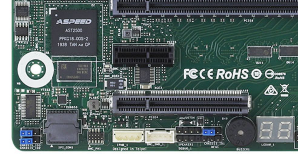
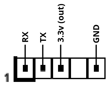
BMC debug header
This header labeled BMC_DEBUG1 provides access to the debug serial port of the AST2500 SoC (UART 5). The UART works with 3.3v level signals and provides a 3.3v output and can be found on the bottom left of the mainboard.
Using this port you can access the U-Boot command prompt, the Linux bootlog and a shell.
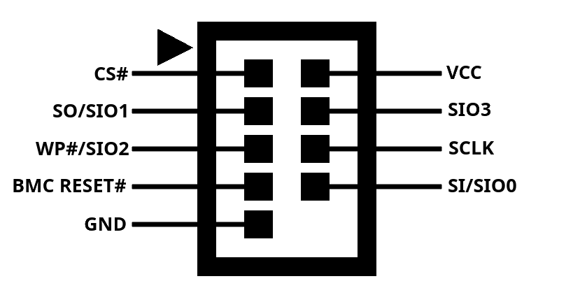
BMC programming header
This header labeled BMC_PH1 provides access to the MX25L51245G 64MB flash chip containing the BMC firmware. Using an exernal SPI flash programmer this port allows for unbricking and easy reflashing of the BMC firmware during development.
This interface uses 3.3v level signals. Connecting the BMC RESET# pin to GND disables the AST2500, allowing an exernal programmer to reprogram the flash chip without interference from the SoC.
Manufacturing mode header
This header labeled MFG1 is connected to GPIO H4 of the AST2500 SoC. With the official firmware installed shorting this jumper makes the BMC boot into a special debug mode, dropping to a root shell on the BMC_DEBUG1 port. When running OpenBMC this GPIO is available for custom applications.
Chassis identification
These three headers labeled CHASSIS_ID1, CHASSIS_ID2 and CHASSIS_ID3 are connected to GPIO G1, G2 and G3 of the AST2500 SoC for ID1, ID2 and ID3 respectively. On production boards these headers appear to not have been installed, but they are functional. When running OpenBMC these GPIOs are available for custom applications.
1.1.2 - ASRock Rack X570D4U mainboard: I2C busses
This page describes the I2C busses and connected on-board devices on the ASRock X570D4U mainboard.
I2C bus 0
This bus is connected to the AUX_PANEL1 connector. SMBus alert for this bus is connected to GPIO 52 (G4) named input-aux-smb-alert-n.
| Device | Address | Available when host is off | Description |
|---|---|---|---|
| AUX panel SMBus header (AUX_PANEL1) | — | Yes | Standard 2.54mm header, pinout is in manual |
I2C bus 1
This bus is used for controlling on-board devices that are used when the host is on.
| Device | Address | Available when host is off | Description |
|---|---|---|---|
| PCA9557 IO expander | 0x1C | No | Controls the FAN fault LEDs |
| Unknown device | 0x1D | No | Unknown |
| Nuvoton NCT6796D-R SuperIO | 0x2D | No | Host temperature monitoring interface (SuperIO) |
| Nuvoton W83773G | 0x4C | Yes | Temperature monitoring interface for 10G NIC (Not installed on base model X570D4U boards) |
PCA9557 IO expander
| Pin | Direction | Function |
|---|---|---|
| 0 | Output | Fault LED for FAN 4 |
| 1 | Output | Fault LED for FAN 5 |
| 2 | Output | Fault LED for FAN 1 |
| 3 | Output | Unknown / not connected |
| 4 | Output | Fault LED for FAN 2 |
| 5 | Output | Fault LED for FAN 3 |
| 6 | Output | Fault LED for FAN 6 |
| 7 | Output | Unknown / not connected |
Nuvoton NCT6796D-R SuperIO
This chip can read the CPU and chipset temperatures. It should be possible to use the newly added nct6775-i2c driver to use this device.
Using the NCT6775-I2C driver
The OpenBMC port for the X570D4U already includes the nct6775-i2c driver in it’s kernel, but as the SuperIO device only appears on the bus when the host system is powered on the driver needs to be loaded in and unloaded based on power state changes. This has not been implemented yet.
The driver can be manually loaded in using the following command:
echo "nct6775 0x2d" > /sys/bus/i2c/devices/i2c-1/new_device
If the driver was loaded correctly then you should now be able to find a folder called hwmon in the device folder /sys/bus/i2c/devices/i2c-1/1-002d. This folder will contain a symlink to the hwmon interface for the SuperIO chip. If the folder is missing then your kernel does not include the nct6775-i2c driver.
Directly accessing and reading the temperature registers
Alternatively the temperatures can be read using this shell script, for which no kernel driver is required:
#!/bin/bash
i2cset -y 1 0x2d 0x4e 0x04
while :
do
    TSI0INT=$((16#$(i2cget -y 1 0x2d 0x09 | cut -f2 -dx)))
    TSI0FRC=$(($((16#$(i2cget -y 1 0x2d 0x0a | cut -f2 -dx)))>>5))
    TSI1INT=$((16#$(i2cget -y 1 0x2d 0x0b | cut -f2 -dx)))
    TSI1FRC=$(($((16#$(i2cget -y 1 0x2d 0x0c | cut -f2 -dx)))>>5))
    echo "TSI0_TEMP: $TSI0INT.$TSI0FRC °C / TSI1_TEMP: $TSI1INT.$TSI1FRC °C"
    sleep 0.5
done
Nuvoton W83773G
This device is available on the versions of the X570D4U which include a 10Gbit network adapter. It monitors the temperature of the 10Gbit NIC.
cat /sys/class/hwmon/hwmon0/temp2_input
I2C bus 2
This bus is used for connecting to exernal power supplies with SMBus monitoring support using the PSU_SMB1 connector. SMBus alert for this bus is connected to GPIO 54 (G6) named input-psu-smb-alert-n.
| Device | Address | Available when host is off | Description |
|---|---|---|---|
| PSU SMBus header (PSU_SMB1) | — | Yes | MOLEX 70543-0003 connector, pinout is in manual |
I2C bus 3
This bus has an unknown purpose.
| Device | Address | Available when host is off | Description |
|---|---|---|---|
| Unknown device | 0x13 | Yes | Unknown |
| Unknown device | 0x14 | No | Unknown |
| Unknown device | 0x15 | No | Unknown |
I2C bus 4
This bus is used to connect to expansion cards inserted into the PCI-Express slots of the mainboard.
| Device | Address | Available when host is off | Description |
|---|---|---|---|
| NXP PCA9545A I2C bus switch | 0x70 | Yes | Bus multiplexer for switching between PCIe slots |
NXP PCA9545A I2C bus switch
| Bus | Port |
|---|---|
| 0 | PCI express 16x slot |
| 1 | PCI express 8x slot |
| 2 | Unknown |
| 3 | PCI express 1x slot |
I2C bus 5
This bus is connected to the BMC_SMB_1 connector. The BMC_PRESENT_1_N signal on the BMC_SMB_1 connector is connected to GPIO 132 (Q4) named input-bmc-smb-present-n.
| Device | Address | Available when host is off | Description |
|---|---|---|---|
| BMC SMbus header (BMC_SMB_1) | — | Yes | Unknown connector, pinout is in manual (might be MOLEX 353620550) |
I2C bus 7
This bus is used for connecting to the FRU EEPROM and the RAM DIMMs.
| Device | Address | Available when host is off | Description |
|---|---|---|---|
| RAM DIMM A1 temperature sensor | 0x1A | No | |
| RAM DIMM A2 temperature sensor | ???? | No | Not tested yet |
| RAM DIMM B1 temperature sensor | 0x1B | No | |
| RAM DIMM B2 temperature sensor | ???? | No | Not tested yet |
| Unknown device | 0x30 | No | Unknown |
| Unknown device | 0x35 | No | Unknown |
| Unknown device | 0x36 | No | Unknown |
| RAM DIMM A1 SPD EEPROM | 0x52 | No | |
| RAM DIMM A2 SPD EEPROM | ???? | No | Not tested yet |
| RAM DIMM B1 SPD EEPROM | 0x53 | No | |
| RAM DIMM B2 SPD EEPROM | ???? | No | Not tested yet |
| FRU EEPROM | 0x57 | Yes |
I2C bus 8
This bus is connected to the IPMB_1 connector.
| Device | Address | Available when host is off | Description |
|---|---|---|---|
| IPMI SMbus header (IPMB_1) | — | Yes | MOLEX 22035045 connector, pinout is in manual |
1.1.3 - ASRock Rack X570D4U mainboard: GPIO
This page describes the GPIOs of the ASPEED AST2500 BMC on the ASRock X570D4U mainboard.
| # | ID | Power domain | Peripheral | Type | Name | Description |
|---|---|---|---|---|---|---|
| 0 | A0 | PV33D | GPIO | Input | input-locatorled-n | State of the locator LED (active low) |
| 1 | A1 | PV33D | ||||
| 2 | A2 | PV33D | ||||
| 3 | A3 | PV33D | ||||
| 4 | A4 | I2C | I2C bus 8 clock (IPMB SMBus) | |||
| 5 | A5 | I2C | I2C bus 8 data (IPMB SMBus) | |||
| 6 | A6 | |||||
| 7 | A7 | |||||
| 8 | B0 | LPVDD | GPIO | Input | input-bios-post-cmplt-n | BIOS has completed POST stage (active low) |
| 9 | B1 | LPVDD | (Changes on host boot) | |||
| 10 | B2 | LPVDD | (Changes on host boot) | |||
| 11 | B3 | LPVDD | ||||
| 12 | B4 | LPVDD | (Changes on host boot) | |||
| 13 | B5 | LPVDD | ||||
| 14 | B6 | LPVDD | ||||
| 15 | B7 | LPVDD | (Changes on host boot) | |||
| 16 | C0 | (I2C bus 9 clock) | ||||
| 17 | C1 | (I2C bus 9 data) | ||||
| 18 | C2 | (I2C bus 10 clock) | ||||
| 19 | C3 | (I2C bus 10 data) | ||||
| 20 | C4 | (I2C bus 11 clock) | ||||
| 21 | C5 | (I2C bus 11 data) | ||||
| 22 | C6 | GPIO | Output open drain | control-locatorbutton-n | Pull low to emulate identification button press | |
| 23 | C7 | |||||
| 24 | D0 | GPIO | Input | button-power-n | State of the power button (active low) | |
| 25 | D1 | GPIO | Output open drain | control-power-n | Pull low to emulate power button press | |
| 26 | D2 | GPIO | Input | button-reset-n | State of the reset button (active low) | |
| 27 | D3 | GPIO | Output open drain | control-reset-n | Pull low to emulate reset button press | |
| 28 | D4 | |||||
| 29 | D5 | |||||
| 30 | D6 | |||||
| 31 | D7 | |||||
| 32 | E0 | (UART3 CTS) | ||||
| 33 | E1 | (UART3 DCD) | ||||
| 34 | E2 | (UART3 DSR) | ||||
| 35 | E3 | (UART3 RING) | ||||
| 36 | E4 | (UART3 DTR) | ||||
| 37 | E5 | (UART3 RTS) | ||||
| 38 | E6 | (UART3 TX) | ||||
| 39 | E7 | (UART3 RX) | ||||
| 40 | F0 | (UART4 CTS, LPC HOST BIT 0) | ||||
| 41 | F1 | (UART4 DCD, LPC HOST BIT 1) | ||||
| 42 | F2 | (UART4 DSR, LPC HOST BIT 2) | ||||
| 43 | F3 | (UART4 RING, LPC HOST BIT 3) | ||||
| 44 | F4 | (UART4 DTR, LPC HOST CLOCK IO) | ||||
| 45 | F5 | (UART4 RTS, LPC HOST FRAME#) | ||||
| 46 | F6 | (UART4 TX, LPC HOST SERIRQ#, maybe BMC_PCH_SCI_LPC) | ||||
| 47 | F7 | (UART4 RX, LPC HOST RESET IO, maybe BMC_NCSI_MUX_STL) | ||||
| 48 | G0 | GPIO | Output | output-hwm-vbat-enable | Pull high to connect the RTC battery to ADC9 | |
| 49 | G1 | GPIO | Input | input-id0-n | Pulled low when jumper ID0 is closed | |
| 50 | G2 | GPIO | Input | input-id1-n | Pulled low when jumper ID1 is closed | |
| 51 | G3 | GPIO | Input | input-id2-n | Pulled low when jumper ID2 is closed | |
| 52 | G4 | GPIO | Input | input-aux-smb-alert-n | SMBus alert for I2C bus 0 (AUX_PANEL1) | |
| 53 | G5 | |||||
| 54 | G6 | GPIO | Input | input-psu-smb-alert-n | SMBus alert for I2C bus 2 (PSU_SMB1) | |
| 55 | G7 | |||||
| 56 | H0 | |||||
| 57 | H1 | |||||
| 58 | H2 | |||||
| 59 | H3 | |||||
| 60 | H4 | GPIO | Input | input-mfg-mode-n | Pulled low when jumper MFG1 is closed | |
| 61 | H5 | |||||
| 62 | H6 | GPIO | Output | led-heartbeat-n | Controls the green heartbeat LED on the board (active low) | |
| 63 | H7 | GPIO | Input | input-case-open-n | High while case open button is pressed, low when released | |
| 64 | I0 | (SYSCS#) | ||||
| 65 | I1 | (SYSCK) | ||||
| 66 | I2 | (SYSMOSI) | ||||
| 67 | I3 | (SYSMISO) | ||||
| 68 | I4 | (SPI1CS0# / VBCS#) | ||||
| 69 | I5 | (SPI1CK / VBCK) | ||||
| 70 | I6 | (SPI1MOSI / VBMOSI) | ||||
| 71 | I7 | (SPI1MISO / VBMISO) | ||||
| 72 | J0 | GPIO | Output | output-bmc-ready-n | Signals to the host that the BMC is ready (active low) | |
| 73 | J1 | (guess based on other asrock boards: BMC_PCH_BIOS_CS_N) | ||||
| 74 | J2 | |||||
| 75 | J3 | |||||
| 76 | J4 | VGA | VGA horizontal sync | |||
| 77 | J5 | VGA | VGA vertical sync | |||
| 78 | J6 | VGA | VGA DDC clock | |||
| 79 | J7 | VGA | VGA DDC data | |||
| 80 | K0 | I2C | I2C bus 4 clock (PCI Express SMBus) | |||
| 81 | K1 | I2C | I2C bus 4 data (PCI Express SMBus) | |||
| 82 | K2 | I2C | I2C bus 5 clock (BMC SMBus) | |||
| 83 | K3 | I2C | I2C bus 5 data (BMC SMBus) | |||
| 84 | K4 | (I2C bus 6 clock) | ||||
| 85 | K5 | (I2C bus 6 data) | ||||
| 86 | K6 | I2C | I2C bus 7 clock (FRU and SPD EEPROM SMBus) | |||
| 87 | K7 | I2C | I2C bus 7 data (FRU and SPD EEPROM SMBus) | |||
| 88 | L0 | (UART1 CTS) | ||||
| 89 | L1 | (UART1 DCD) | ||||
| 90 | L2 | (UART1 DSR) | ||||
| 91 | L3 | (UART1 RING) | ||||
| 92 | L4 | (UART1 DTR) | ||||
| 93 | L5 | (UART1 RTS) | ||||
| 94 | L6 | (UART1 TX) | ||||
| 95 | L7 | (UART1 RX) | ||||
| 96 | M0 | (UART2 CTS) | ||||
| 97 | M1 | (UART2 DCD) | ||||
| 98 | M2 | (UART2 DSR) | ||||
| 99 | M3 | (UART2 RING) | ||||
| 100 | M4 | (UART2 DTR) | ||||
| 101 | M5 | (UART2 RTS) | ||||
| 102 | M6 | (UART2 TX) | ||||
| 103 | M7 | (UART2 RX) | ||||
| 104 | N0 | PWM | FAN1 PWM output | |||
| 105 | N1 | PWM | FAN2 PWM output | |||
| 106 | N2 | PWM | FAN3 PWM output | |||
| 107 | N3 | PWM | FAN4 PWM output | |||
| 108 | N4 | PWM | FAN6 PWM output | |||
| 109 | N5 | PWM | FAN5 PWM output | |||
| 110 | N6 | |||||
| 111 | N7 | |||||
| 112 | O0 | Tachometer | FAN1 tachometer input | |||
| 113 | O1 | Tachometer | FAN2 tachometer input | |||
| 114 | O2 | Tachometer | FAN3 tachometer input | |||
| 115 | O3 | Tachometer | FAN4 tachometer input 1 | |||
| 116 | O4 | Tachometer | FAN5 tachometer input 1 | |||
| 117 | O5 | Tachometer | FAN6 tachometer input 1 | |||
| 118 | O6 | |||||
| 119 | O7 | |||||
| 120 | P0 | |||||
| 121 | P1 | |||||
| 122 | P2 | |||||
| 123 | P3 | Tachometer | FAN4 tachometer input 2 | |||
| 124 | P4 | Tachometer | FAN5 tachometer input 2 | |||
| 125 | P5 | Tachometer | FAN6 tachometer input 2 | |||
| 126 | P6 | |||||
| 127 | P7 | |||||
| 128 | Q0 | I2C | I2C bus 2 clock (PSU_SMB1) | |||
| 129 | Q1 | I2C | I2C bus 2 data (PSU_SMB1) | |||
| 130 | Q2 | I2C | I2C bus 3 clock | |||
| 131 | Q3 | I2C | I2C bus 3 data | |||
| 132 | Q4 | GPIO | Input | input-bmc-smb-present-n | BMC present input (BMC_SMB_1) | |
| 133 | Q5 | |||||
| 134 | Q6 | PV33D | ||||
| 135 | Q7 | PV33D | GPIO | Input | input-pcie-wake-n | Pulled low when a PCI Express card asserts WAKE# |
| 136 | R0 | |||||
| 137 | R1 | |||||
| 138 | R2 | (SPI2CS0#) | ||||
| 139 | R3 | (SPI2CK) | ||||
| 140 | R4 | (SPI2MOSI) | ||||
| 141 | R5 | (SPI2MISO) | ||||
| 142 | R6 | RGMII | MDC1 | |||
| 143 | R7 | RGMII | MDIO1 | |||
| 144 | S0 | PV33D | GPIO | Input | input-bmc-pchhot-n | Needs verification |
| 145 | S1 | PV33D | ||||
| 146 | S2 | PV33D | ||||
| 147 | S3 | PV33D | ||||
| 148 | S4 | PV33D | ||||
| 149 | S5 | PV33D | ||||
| 150 | S6 | PV33D | ||||
| 151 | S7 | PV33D | ||||
| 152 | T0 | RGMII | Dedicated LAN port: TXCK | |||
| 153 | T1 | RGMII | Dedicated LAN port: TXCL | |||
| 154 | T2 | RGMII | Dedicated LAN port: TXD0 | |||
| 155 | T3 | RGMII | Dedicated LAN port: TXD1 | |||
| 156 | T4 | RGMII | Dedicated LAN port: TXD2 | |||
| 157 | T5 | RGMII | Dedicated LAN port: TXD3 | |||
| 158 | T6 | RMII | NC-SI: RCLKO | |||
| 159 | T7 | RMII | NC-SI: TXEN | |||
| 160 | U0 | RMII | NC-SI: TXD0 | |||
| 161 | U1 | RMII | NC-SI: TXD1 | |||
| 162 | U2 | |||||
| 163 | U3 | |||||
| 164 | U4 | RGMII | Dedicated LAN port: RXCK | |||
| 165 | U5 | RGMII | Dedicated LAN port: RXCTL | |||
| 166 | U6 | RGMII | Dedicated LAN port: RXD0 | |||
| 167 | U7 | RGMII | Dedicated LAN port: RXD1 | |||
| 168 | V0 | RGMII | Dedicated LAN port: RXD2 | |||
| 169 | V1 | RGMII | Dedicated LAN port: RXD3 | |||
| 170 | V2 | RMII | NC-SI: CLKI | |||
| 171 | V3 | |||||
| 172 | V4 | RMII | NC-SI: RXD0 | |||
| 173 | V5 | RMII | NC-SI: RXD1 | |||
| 174 | V6 | RMII | NC-SI: CRSDV | |||
| 175 | V7 | RMII | NC-SI: RXER | |||
| 176 | W0 | ADC | Analog input representing 3VSB | |||
| 177 | W1 | ADC | Analog input representing 5VSB | |||
| 178 | W2 | ADC | Analog input representing VCPU | |||
| 179 | W3 | ADC | Analog input representing VSOC | |||
| 180 | W4 | ADC | Analog input representing VCCM | |||
| 181 | W5 | ADC | Analog input representing APU VDDP | |||
| 182 | W6 | ADC | Analog input representing PM VDD CLDO | |||
| 183 | W7 | ADC | Analog input representing PM VDDCR S5 | |||
| 184 | X0 | ADC | Analog input representing PM VDDCR | |||
| 185 | X1 | ADC | Analog input representing RTC battery voltage | |||
| 186 | X2 | ADC | Analog input representing 3V | |||
| 187 | X3 | ADC | Analog input representing 5V | |||
| 188 | X4 | ADC | Analog input representing 12V | |||
| 189 | X5 | (ADC) | ||||
| 190 | X6 | (ADC) | ||||
| 191 | X7 | (ADC) | ||||
| 192 | Y0 | PV33D | GPIO | Input | input-sleep-s3-n | Rising edge when host starts, not verified |
| 193 | Y1 | PV33D | GPIO | Input | input-sleep-s5-n | Rising edge when host starts, not verified |
| 194 | Y2 | PV33D | ||||
| 195 | Y3 | PV33D | ||||
| 196 | Y4 | I2C | I2C bus 0 clock (AUX_PANEL1) | |||
| 197 | Y5 | I2C | I2C bus 0 data (AUX_PANEL1) | |||
| 198 | Y6 | I2C | I2C bus 1 clock (SuperIO and thermal sensor) | |||
| 199 | Y7 | I2C | I2C bus 1 data (SuperIO and thermal sensor) | |||
| 200 | Z0 | PV33D | ||||
| 201 | Z1 | PV33D | ||||
| 202 | Z2 | PV33D | GPIO | Output | led-fault-n | |
| 203 | Z3 | PV33D | GPIO | Output | output-bmc-throttle-n | Needs verification |
| 204 | Z4 | PV33D | ||||
| 205 | Z5 | PV33D | ||||
| 206 | Z6 | PV33D | ||||
| 207 | Z7 | PV33D | ||||
| 208 | AA0 | PV33D | GPIO | Input | input-cpu1-thermtrip-latch-n | |
| 209 | AA1 | PV33D | ||||
| 210 | AA2 | PV33D | GPIO | Input | input-cpu1-prochot-n | |
| 211 | AA3 | PV33D | ||||
| 212 | AA4 | PV33D | ||||
| 213 | AA5 | PV33D | ||||
| 214 | AA6 | PV33D | ||||
| 215 | AA7 | PV33D | ||||
| 216 | AB0 | PV33D | ||||
| 217 | AB1 | PV33D | GPIO | Input | input-power-good | Rising edge when host starts, not verified |
| 218 | AB2 | PV33D | ||||
| 219 | AB3 | PV33D | ||||
| 220 | — | |||||
| 221 | — | |||||
| 222 | — | |||||
| 223 | — | |||||
| 224 | AC0 | LPC | LAD0 | |||
| 225 | AC1 | LPC | LAD1 | |||
| 226 | AC2 | LPC | LAD2 | |||
| 227 | AC3 | LPC | LAD3 | |||
| 228 | AC4 | LPC | Clock | |||
| 229 | AC5 | LPC | LFRAME | |||
| 230 | AC6 | LPC | IRQ | |||
| 231 | AC7 | LPC | Reset |
1.1.4 - Programming SPI flash with an FT2232 breakout board
Connection diagram
| Pin on Mainboard | Function SPI | Function QSPI | Pin on FTDI |
|---|---|---|---|
| CS# | Chip select | Chip select | ADBUS 3 |
| VCC | 3.3v output | 3.3v output | Not connected |
| SO/SIO1 | Data output | Data bit 1 | ADBUS 2 |
| SIO3 | Unused | Data bit 3 | Not connected |
| WP#/SIO2 | Write protect | Data bit 2 | Not connected |
| SCLK | Clock | Clock | ADBUS 0 |
| BMC RESET# | Reset | Reset | Ground |
| SI/SIO0 | Data input | Data bit 0 | ADBUS 1 |
| GND | Ground | Ground | Ground |
1.1.5 - ASRock Rack X570D4U mainboard: temperature sensors
This page describes the temperature sensors on the X570D4U.
Nuvoton NCT6796D-R SuperIO
This device can be accessed via I2C bus 1 at address 0x2D.
| Input | Valid | Description |
|---|---|---|
| SYSTIN | Yes | Close to SuperIO chip, could be MB temperature |
| CPUTIN | No | |
| AUXTIN0 | No | |
| AUXTIN1 | Yes | Close to SuperIO chip, could be MB temperature |
| AUXTIN2 | Yes | Bottom left corner of the board, Card side temperature |
| AUXTIN3 | No | |
| AUXTIN4 | No | |
| TSI0_TEMP | Yes | CPU temperature |
| TSI1_TEMP | Yes | Chipset temperature |
Nuvoton W83773G
This device can be accessed via I2C bus 1 at address 0x4C.
| Input | Valid | Description |
|---|---|---|
| temp1_input | Yes | Inside of the W83773G, located close to the 10Gbit NIC |
| temp2_input | Yes | Cconnected to a temperature diode in or close to the 10Gbit NIC |
| temp3_input | No |
1.1.6 - ASRock Rack X570D4U mainboard: fans
This page describes the fan connectors on the X570D4U.
Fan connectors
| Connector | PWM | Tacho 1 | Tacho 2 |
|---|---|---|---|
| 1 | 1 | 1 | - |
| 2 | 2 | 2 | - |
| 3 | 3 | 3 | - |
| 4 | 4 | 4 | 12 |
| 5 | 6 | 5 | 13 |
| 6 | 5 | 6 | 14 |
Fan 1-3 connector pinout
| Pin | Function | Asrock label |
|---|---|---|
| 1 | Ground | GND |
| 2 | Power | FAN_VOLTAGE |
| 3 | Tacho 1 | FAN_SPEED |
| 4 | PWM | FAN_SPEED_CONTROL |
Fan 4-6 connector pinout
| Pin | Function | Asrock label |
|---|---|---|
| 1 | Ground | GND |
| 2 | Power | FAN_VOLTAGE |
| 3 | Tacho 1 | FAN_SPEED |
| 4 | PWM | FAN_SPEED_CONTROL |
| 5 | Tacho 2 | SENSOR |
| 6 | - | NC |
1.2 - ASRock Rack PAUL
Project status: in progress
The ASRock Rack PAUL is a PCI-express add-in card for servers and workstations containing an Aspeed AST2500 BMC chip. A Baseboard Management Controller (BMC) is a small computer that allows for out-of-band management. It allows for remote power control, KVM (remote keyboard, video and mouse) control, virtual media insertion and much more.
| Property | Value | Part |
|---|---|---|
| Processor | ARM1176JZS (ARMv6) @ 800MHz | AST2500 SoC |
| RAM | 512MB DDR4 | K4A4G165WE-BCRC |
| Storage | 3x 32MB SPI flash | MX25L25645G |
These parts make for quite a powerful system, unfortunately the operating system shipped by ASRock Rack is proprietary and dos not allow for easy modification. To allow for a more secure, transparent and customizable experience we are working on adding support for this mainboard to the mainline Linux kernel and the OpenBMC Linux distribution for BMCs.
Official documentation is provided in ASRock Racks manual.
1.2.1 - ASRock Rack PAUL: GPIO
This page describes the GPIOs of the ASPEED AST2500 BMC on the ASRock Rack Paul card.
| # | ID | Power domain | Peripheral | Type | Name | Description | Verified |
|---|---|---|---|---|---|---|---|
| 0 | A0 | PV33D | |||||
| 1 | A1 | PV33D | |||||
| 2 | A2 | PV33D | GPIO | Input | input-nmi | NMI input on pinheader | Yes |
| 3 | A3 | PV33D | |||||
| 4 | A4 | I2C | I2C bus 8 clock (IPMB_1) | Yes | |||
| 5 | A5 | I2C | I2C bus 8 data (IPMB_1) | Yes | |||
| 6 | A6 | ||||||
| 7 | A7 | ||||||
| 8 | B0 | LPVDD | |||||
| 9 | B1 | LPVDD | |||||
| 10 | B2 | LPVDD | |||||
| 11 | B3 | LPVDD | |||||
| 12 | B4 | LPVDD | |||||
| 13 | B5 | LPVDD | |||||
| 14 | B6 | LPVDD | |||||
| 15 | B7 | LPVDD | |||||
| 16 | C0 | SD card | SD card 1: CLK | Yes | |||
| 17 | C1 | SD card | SD card 1: CMD | Yes | |||
| 18 | C2 | SD card | SD card 1: DAT0 | Yes | |||
| 19 | C3 | SD card | SD card 1: DAT1 | Yes | |||
| 20 | C4 | SD card | SD card 1: DAT2 | Yes | |||
| 21 | C5 | SD card | SD card 1: DAT3 | Yes | |||
| 22 | C6 | SD card | SD card 1: CD# | Yes | |||
| 23 | C7 | ||||||
| 24 | D0 | GPIO | Input | button-power-n | AUX_PANEL1 pin 1 | Yes | |
| 25 | D1 | GPIO | Output open drain | control-power-n | AUX_PANEL1 pin 3 | Yes | |
| 26 | D2 | GPIO | Input | button-reset-n | AUX_PANEL1 pin 5 | Yes | |
| 27 | D3 | GPIO | Output open drain | control-reset-n | AUX_PANEL1 pin 7 | Yes | |
| 28 | D4 | GPIO | aux-panel-1-9 | AUX_PANEL1 pin 9 | Yes | ||
| 29 | D5 | GPIO | aux-panel-1-11 | AUX_PANEL1 pin 11 | Yes | ||
| 30 | D6 | GPIO | aux-panel-1-15 | AUX_PANEL1 pin 15 | Yes | ||
| 31 | D7 | GPIO | aux-panel-1-17 | AUX_PANEL1 pin 17 | Yes | ||
| 32 | E0 | (UART3 CTS) | |||||
| 33 | E1 | (UART3 DCD) | |||||
| 34 | E2 | (UART3 DSR) | |||||
| 35 | E3 | (UART3 RING) | |||||
| 36 | E4 | (UART3 DTR) | |||||
| 37 | E5 | (UART3 RTS) | |||||
| 38 | E6 | (UART3 TX) | |||||
| 39 | E7 | (UART3 RX) | |||||
| 40 | F0 | (UART4 CTS, LPC HOST BIT 0) | |||||
| 41 | F1 | (UART4 DCD, LPC HOST BIT 1) | |||||
| 42 | F2 | (UART4 DSR, LPC HOST BIT 2) | |||||
| 43 | F3 | (UART4 RING, LPC HOST BIT 3) | |||||
| 44 | F4 | (UART4 DTR, LPC HOST CLOCK IO) | |||||
| 45 | F5 | (UART4 RTS, LPC HOST FRAME#) | |||||
| 46 | F6 | (UART4 TX, LPC HOST SERIRQ#, maybe BMC_PCH_SCI_LPC) | |||||
| 47 | F7 | GPIO | Output | output-bios-flash-select | Switches SPI1 between the BIOS flash chip and BIOS_PH1 | Yes | |
| 48 | G0 | GPIO | Output | ||||
| 49 | G1 | ||||||
| 50 | G2 | ||||||
| 51 | G3 | ||||||
| 52 | G4 | GPIO | Input | input-aux-smb-alert-n | SMBus alert for I2C bus 5 (AUX_PANEL2) | Yes | |
| 53 | G5 | ||||||
| 54 | G6 | GPIO | Input | input-psu-smb-alert-n | SMBus alert for I2C bus 3 (PSU_SMB1) | Yes | |
| 55 | G7 | ||||||
| 56 | H0 | ||||||
| 57 | H1 | ||||||
| 58 | H2 | ||||||
| 59 | H3 | ||||||
| 60 | H4 | GPIO | Input | input-mfg-mode-n | Pulled low when jumper MFG1 is closed | Yes | |
| 61 | H5 | ||||||
| 62 | H6 | GPIO | Output | led-heartbeat-n | Controls the green heartbeat LED on the board (active low) | Yes | |
| 63 | H7 | ||||||
| 64 | I0 | (SYSCS#) | |||||
| 65 | I1 | (SYSCK) | |||||
| 66 | I2 | (SYSMOSI) | |||||
| 67 | I3 | (SYSMISO) | |||||
| 68 | I4 | SPI | CS | SPI1CS0# / VBCS# | Yes | ||
| 69 | I5 | SPI | SCK | SPI1CK / VBCK | Yes | ||
| 70 | I6 | SPI | MOSI | SPI1MOSI / VBMOSI | Yes | ||
| 71 | I7 | SPI | MISO | SPI1MISO / VBMISO | Yes | ||
| 72 | J0 | ||||||
| 73 | J1 | ||||||
| 74 | J2 | ||||||
| 75 | J3 | ||||||
| 76 | J4 | VGA | VGA horizontal sync | ||||
| 77 | J5 | VGA | VGA vertical sync | ||||
| 78 | J6 | VGA | VGA DDC clock | ||||
| 79 | J7 | VGA | VGA DDC data | ||||
| 80 | K0 | I2C | I2C bus 4 clock (temperature sensor) | Yes | |||
| 81 | K1 | I2C | I2C bus 4 data (temperature sensor) | Yes | |||
| 82 | K2 | I2C | I2C bus 5 clock (AUX_PANEL2) | Yes | |||
| 83 | K3 | I2C | I2C bus 5 data (AUX_PANEL2) | Yes | |||
| 84 | K4 | (I2C bus 6 clock) | |||||
| 85 | K5 | (I2C bus 6 data) | |||||
| 86 | K6 | I2C | I2C bus 7 clock (FRU and SPD EEPROM SMBus) | ||||
| 87 | K7 | I2C | I2C bus 7 data (FRU and SPD EEPROM SMBus) | ||||
| 88 | L0 | (UART1 CTS) | |||||
| 89 | L1 | (UART1 DCD) | |||||
| 90 | L2 | (UART1 DSR) | |||||
| 91 | L3 | (UART1 RING) | |||||
| 92 | L4 | (UART1 DTR) | |||||
| 93 | L5 | (UART1 RTS) | |||||
| 94 | L6 | (UART1 TX) | |||||
| 95 | L7 | (UART1 RX) | |||||
| 96 | M0 | (UART2 CTS) | |||||
| 97 | M1 | (UART2 DCD) | |||||
| 98 | M2 | (UART2 DSR) | |||||
| 99 | M3 | (UART2 RING) | |||||
| 100 | M4 | (UART2 DTR) | |||||
| 101 | M5 | (UART2 RTS) | |||||
| 102 | M6 | (UART2 TX) | |||||
| 103 | M7 | (UART2 RX) | |||||
| 104 | N0 | PWM | |||||
| 105 | N1 | PWM | FAN1 PWM output (pwm2) | Yes | |||
| 106 | N2 | PWM | FAN2 PWM output (pwm3) | Yes | |||
| 107 | N3 | PWM | |||||
| 108 | N4 | PWM | |||||
| 109 | N5 | PWM | |||||
| 110 | N6 | ||||||
| 111 | N7 | ||||||
| 112 | O0 | Tachometer | |||||
| 113 | O1 | Tachometer | FAN1 tachometer input (in2) | Yes | |||
| 114 | O2 | Tachometer | FAN2 tachometer input (in3) | Yes | |||
| 115 | O3 | Tachometer | |||||
| 116 | O4 | Tachometer | |||||
| 117 | O5 | Tachometer | |||||
| 118 | O6 | ||||||
| 119 | O7 | ||||||
| 120 | P0 | ||||||
| 121 | P1 | ||||||
| 122 | P2 | ||||||
| 123 | P3 | Tachometer | |||||
| 124 | P4 | Tachometer | |||||
| 125 | P5 | Tachometer | |||||
| 126 | P6 | ||||||
| 127 | P7 | ||||||
| 128 | Q0 | I2C | I2C bus 2 clock (BMC_SMB_2) | Yes | |||
| 129 | Q1 | I2C | I2C bus 2 data (BMC_SMB_2) | Yes | |||
| 130 | Q2 | I2C | I2C bus 3 clock (PSU_SMB1) | Yes | |||
| 131 | Q3 | I2C | I2C bus 3 data (PSU_SMB1) | Yes | |||
| 132 | Q4 | GPIO | Input | input-bmc-smb-present-1-n | BMC present input (BMC_SMB_1) | Yes | |
| 133 | Q5 | GPIO | Input | input-bmc-smb-present-2-n | BMC present input (BMC_SMB_2) | Yes | |
| 134 | Q6 | PV33D | |||||
| 135 | Q7 | PV33D | GPIO | Output | output-pcie-wake-n | PCI Express WAKE# | Yes |
| 136 | R0 | ||||||
| 137 | R1 | ||||||
| 138 | R2 | (SPI2CS0#) | |||||
| 139 | R3 | (SPI2CK) | |||||
| 140 | R4 | (SPI2MOSI) | |||||
| 141 | R5 | (SPI2MISO) | |||||
| 142 | R6 | RGMII | MDC1 | ||||
| 143 | R7 | RGMII | MDIO1 | ||||
| 144 | S0 | PV33D | |||||
| 145 | S1 | PV33D | |||||
| 146 | S2 | PV33D | |||||
| 147 | S3 | PV33D | |||||
| 148 | S4 | PV33D | |||||
| 149 | S5 | PV33D | |||||
| 150 | S6 | PV33D | |||||
| 151 | S7 | PV33D | |||||
| 152 | T0 | RGMII | Dedicated LAN port: TXCK | Yes | |||
| 153 | T1 | RGMII | Dedicated LAN port: TXCL | Yes | |||
| 154 | T2 | RGMII | Dedicated LAN port: TXD0 | Yes | |||
| 155 | T3 | RGMII | Dedicated LAN port: TXD1 | Yes | |||
| 156 | T4 | RGMII | Dedicated LAN port: TXD2 | Yes | |||
| 157 | T5 | RGMII | Dedicated LAN port: TXD3 | Yes | |||
| 158 | T6 | RMII | NC-SI: RCLKO | ||||
| 159 | T7 | RMII | NC-SI: TXEN | Yes | |||
| 160 | U0 | RMII | NC-SI: TXD0 | Yes | |||
| 161 | U1 | RMII | NC-SI: TXD1 | Yes | |||
| 162 | U2 | ||||||
| 163 | U3 | ||||||
| 164 | U4 | RGMII | Dedicated LAN port: RXCK | Yes | |||
| 165 | U5 | RGMII | Dedicated LAN port: RXCTL | Yes | |||
| 166 | U6 | RGMII | Dedicated LAN port: RXD0 | Yes | |||
| 167 | U7 | RGMII | Dedicated LAN port: RXD1 | Yes | |||
| 168 | V0 | RGMII | Dedicated LAN port: RXD2 | Yes | |||
| 169 | V1 | RGMII | Dedicated LAN port: RXD3 | Yes | |||
| 170 | V2 | RMII | NC-SI: CLKI | ||||
| 171 | V3 | ||||||
| 172 | V4 | RMII | NC-SI: RXD0 | Yes | |||
| 173 | V5 | RMII | NC-SI: RXD1 | Yes | |||
| 174 | V6 | RMII | NC-SI: CRSDV | Yes | |||
| 175 | V7 | RMII | NC-SI: RXER | ||||
| 176 | W0 | ADC | Analog input representing 3VSB | ||||
| 177 | W1 | ADC | Analog input representing 5VSB | ||||
| 178 | W2 | ADC | Analog input representing VCPU | ||||
| 179 | W3 | ADC | Analog input representing VSOC | ||||
| 180 | W4 | ADC | Analog input representing VCCM | ||||
| 181 | W5 | ADC | Analog input representing APU VDDP | ||||
| 182 | W6 | ADC | Analog input representing PM VDD CLDO | ||||
| 183 | W7 | ADC | Analog input representing PM VDDCR S5 | ||||
| 184 | X0 | ADC | Analog input representing PM VDDCR | ||||
| 185 | X1 | ADC | Analog input representing RTC battery voltage | ||||
| 186 | X2 | ADC | Analog input representing 3V | ||||
| 187 | X3 | ADC | Analog input representing 5V | ||||
| 188 | X4 | ADC | Analog input representing 12V | ||||
| 189 | X5 | (ADC) | |||||
| 190 | X6 | (ADC) | |||||
| 191 | X7 | (ADC) | |||||
| 192 | Y0 | PV33D | GPIO | aux-panel-2-11 | AUX_PANEL2 pin 11 | Yes | |
| 193 | Y1 | PV33D | GPIO | aux-panel-2-15 | AUX_PANEL2 pin 15 | Yes | |
| 194 | Y2 | PV33D | GPIO | aux-panel-2-17 | AUX_PANEL2 pin 17 | Yes | |
| 195 | Y3 | PV33D | GPIO | Output | led-fault-n | Red LED indicating system error & AUX_PANEL2 pin 19 | Yes |
| 196 | Y4 | I2C | I2C bus 0 clock (PCI express) | Yes | |||
| 197 | Y5 | I2C | I2C bus 0 data (PCI express) | Yes | |||
| 198 | Y6 | I2C | I2C bus 1 clock (BMC_SMB_1) | Yes | |||
| 199 | Y7 | I2C | I2C bus 1 data (BMC_SMB_1) | Yes | |||
| 200 | Z0 | PV33D | GPIO | aux-panel-2-3 | AUX_PANEL2 pin 3 | Yes | |
| 201 | Z1 | PV33D | GPIO | aux-panel-2-5 | AUX_PANEL2 pin 5 | Yes | |
| 202 | Z2 | PV33D | GPIO | aux-panel-2-7 | AUX_PANEL2 pin 7 | Yes | |
| 203 | Z3 | PV33D | GPIO | aux-panel-2-9 | AUX_PANEL2 pin 9 | Yes | |
| 204 | Z4 | PV33D | |||||
| 205 | Z5 | PV33D | |||||
| 206 | Z6 | PV33D | |||||
| 207 | Z7 | PV33D | |||||
| 208 | AA0 | PV33D | GPIO | Output | led-fan1-fault | Red LED indicating fault in FAN 1 | Yes |
| 209 | AA1 | PV33D | GPIO | Output | led-fan2-fault | Red LED indicating fault in FAN 2 | Yes |
| 210 | AA2 | PV33D | |||||
| 211 | AA3 | PV33D | |||||
| 212 | AA4 | PV33D | |||||
| 213 | AA5 | PV33D | |||||
| 214 | AA6 | PV33D | |||||
| 215 | AA7 | PV33D | |||||
| 216 | AB0 | PV33D | |||||
| 217 | AA1 | PV33D | |||||
| 218 | AA2 | PV33D | |||||
| 219 | AA3 | PV33D | |||||
| 220 | — | —- | |||||
| 221 | — | —- | |||||
| 222 | — | —- | |||||
| 223 | — | —- | |||||
| 224 | AC0 | LPC | LAD0 | Yes | |||
| 225 | AC1 | LPC | LAD1 | Yes | |||
| 226 | AC2 | LPC | LAD2 | Yes | |||
| 227 | AC3 | LPC | LAD3 | Yes | |||
| 228 | AC4 | LPC | Clock | Yes | |||
| 229 | AC5 | LPC | LFRAME | Yes | |||
| 230 | AC6 | LPC | IRQ | ||||
| 231 | AC7 | LPC | Reset | Yes |