This is the multi-page printable view of this section. Click here to print.

Return to the regular view of this page.

Tanmatsu: hardware

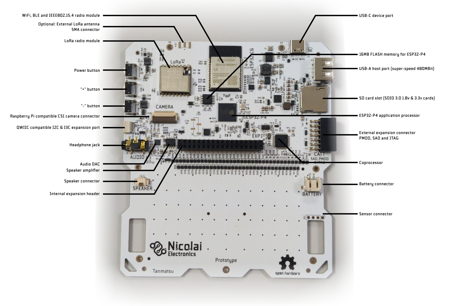
This page describes all the hardware on the Tanmatsu main board, explaining how everything is connected.

Block diagram

The ESP32-P4 application processor is the star of the show, this is the processor that will run your applications.

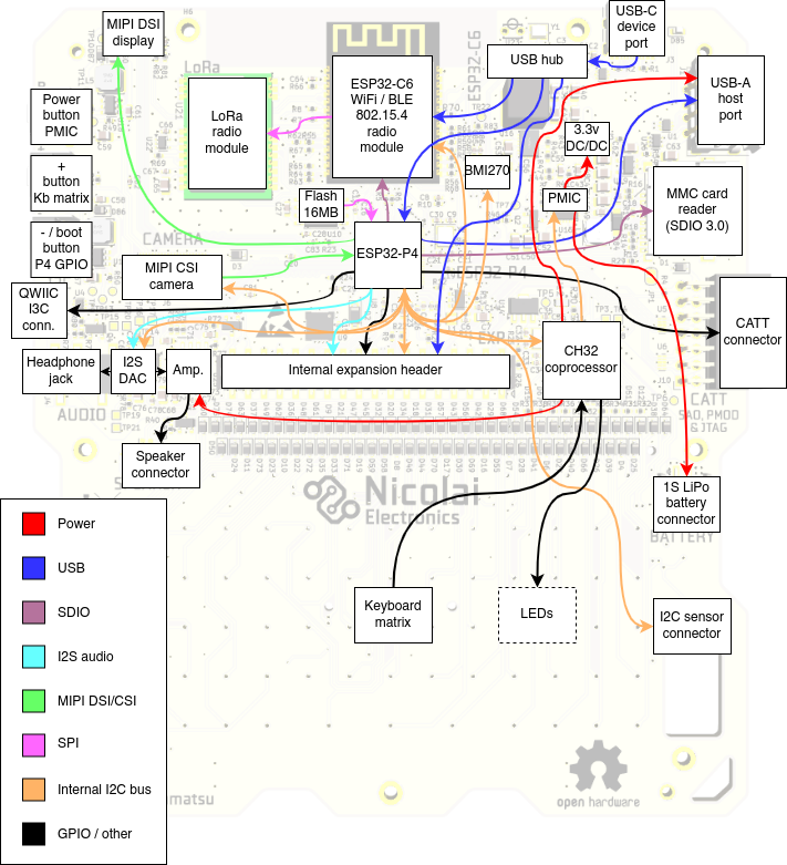
It is directly connected to a lot of peripherals:

  • Quad SPI interface to a 16MB flash chip for storing firmware, apps and data
  • MIPI DSI and CSI interfaces to the display and camera ports
  • Multiple USB interfaces: as device to the USB-C port via the hub and as host to the USB-A port and the internal expansion header
  • Multiple SDIO interfaces: to the MMC card reader and the ESP32-C6 radio module
  • I2C/I3C interface: to the QWIIC port
  • I2C interface: to an I2C bus connecting all the peripherals on the main board to each other

LEDs

Tanmatu has seven LEDs, six of which are addressable RGB LEDs located on the left and right sides of the screen. The seventh LED is located on the back of the board next to the USB-C connector.

The addressable LEDs are fully user controllable by writing the relevant registers of the coprocessor via the internal I2C bus. By default the coprocessor controls the LEDs automatically, this can of course be disabled.

When in automatic control mode the LEDs have the following meaning:

  • the “power” LED (top left) indicates the state of the power management subsystem. Blue indicates the device is running on battery power, orange means the battery is being charged via the USB-C connector, green means the battery is fully charged and red means the device is powered via USB but no battery is detected.
  • The “radio” LED (middle left) indicates the state of the ESP32-C6 radio module. When the radio module is disabled the LED is off, when the radio module is enabled and running normally the led is green and when the radio module is started in bootloader mode for flashing its firmware the led turns blue.
  • The “A” LED (middle right) indicates the state of the USB-A port power output. It is blue when the USB-A port is enabled and off when disabled.
  • The “C” LED (top right) turns red when the power button is pressed.

All other LEDs are currently not automatically controlled.

The “message” LED (bottom left) is meant to allow for indicating that an unread message is available to be read, for example after the radio module receives a message via WiFi, BLE, 802.15.4 mesh or LoRa while the ESP32-P4 application processor is running an app.

The “A”, “B” and “C” LEDs are, aside from the above mentioned automatic control states for the “A” and “C” LEDs meant to show custom states defined by the running application.

The seventh LED is a single color red LED located on the back of the device. This LED is controlled by the power management chip and indicates the state of the power circuit.

It is:

  • Off when the battery is not charging
  • On when the battery is being charged
  • Blinks slowly when a fault has occurred (battery charging is automatically stopped)
  • Blinks rapidly when it attempts to charge the battery while no battery is attached

Expected behavior is that the LED blinks rapidly for a second when powering the board using the USB-C connector while there is no battery connected before turning off once the coprocessor starts up and instructs the power management chip to stop charging. If the LED continues to blink rapidly this could indicate that the coprocessor is not functioning.

Buttons

Tanmatsu has three buttons on the right side of the device. From top to bottom these buttons have the following functions:

  • Power button: hold for two seconds to power on or off the device
  • + button: currently unused, mapped to the BSP_INPUT_NAVIGATION_KEY_VOLUME_UP navigation event in the board support package (BSP) software component
  • - button: functions as bootloader trigger for the ESP32-P4 when pressed while powering on the device. Otherwise currently unused, mapped to the BSP_INPUT_NAVIGATION_KEY_VOLUME_DOWN navigation event in the board support package (BSP) software component

The + button as well as all the keys of the keyboard on the front of the device are wired up as a diode matrix and connected to the coprocessor. The power button is connected directly to the PMIC power management chip and the state of the power button can be read by the coprocessor. The state of the power button is presented to the application by the board support (BSP) component as the BSP_INPUT_ACTION_TYPE_POWER_BUTTON action event.

The - button is directly connected to GPIO35 of the ESP32-P4 and is mapped to the BSP_INPUT_NAVIGATION_KEY_VOLUME_DOWN navigation event in the board support package (BSP) software component.

All the keyboard buttons are mapped to INPUT_EVENT_TYPE_SCANCODE events by the board support component (BSP), presenting a PC keyboard compatible scancode. In addition the BSP presents the keyboard buttons as INPUT_EVENT_TYPE_NAVIGATION and INPUT_EVENT_TYPE_KEYBOARD events too. Navigation keys trigger the navigation event while the letters and numbers trigger the keyboard event. The keyboard event contains the character on the keyboard button both as ASCII char and UTF-8 string, automatically incorporating the state of the modifier keys (SHIFT and ALT GR).

Connectors

Annotated photo of back of PCB

Display connector

Hidden under the front panel a board to board connector connects the display to the main board. The display is pre-installed from the factory so normally you should not need to do anything with this connector.

The connector has the following signals:

  • Three MIPI DSI differential pairs (two for data and one for clock)
  • 3.3v power for the digital logic in the display
  • a 20mA at around 24v supply rail for the backlight LEDs

The output current of the power regulator for the display backlight is controlled by the coprocessor with a PWM signal. You can set the backlight brightness by writing the display backlight brightness register exposed by the coprocessor on the internal I2C bus.

Camera connector

The camera connector is used to connect a CSI camera module. It is pinout-compatible with the camera connector on the Raspberry Pi Zero and 5. Note that software support is limited to a subset of Raspberry Pi compatible camera module sensor chips such as OV5647.

The connector has the following signals:

  • Three MIPI CSI differential pairs (two for data and one for clock)
  • 3.3v power for the camera module
  • Enable signal (shared with the enable signal for the ESP32-C6 radio module)
  • LED control signal (shared with internal expansion port pin E2)

USB-C device port

This port is used to charge the battery, to program and debug the ESP32-P4 and ESP32-C6 microcontrollers and to install apps and browse files from your computer.

It is connected to a USB hub chip which splits the USB port into three interfaces:

  • ESP32-P4 FS (12Mbit) USB port 1 (by default USB serial / JTAG)
  • ESP32-C6 USB serial / JTAG port
  • The internal expansion header

By default the ESP32-P4 exposes a USB serial/JTAG debugging peripheral via the USB-C port. This allows for flashing the ESP32-P4 even if no valid firmware is installed.

The firmware on the ESP32-P4 can swap this USB interface with a customizable USB interface, allowing for exposing other interfaces to the host PC. The launcher firmware includes a USB interface called BadgeLink which allows you to manage the device using a set of Python scripts and using WebUSB in the Chrome and Edge browsers.

To force the ESP32-P4 into a bootloader mode simply hold down the third (-) button on the right side of Tanmatsu down while powering on the device. An easy way to do this is to turn off Tanmatsu by pressing the power button until the device turns off, then press and hold the - while plugging in an USB cable into a PC. After plugging in the USB cable the device powers on, the screen will stay black.

USB-A host port

This port can be used to connect a USB device. The 5 volt power output is is limited to 1A of current and protected against short circuits.

The USB-A port can be disabled and enabled by writing the relevant register of the coprocessor via the internal I2C bus. Note that the enable signal for the USB-A port is shared with the boot mode control pin of the ESP32-C6 radio module. When the ESP32-C6 radio gets enabled the USB-A port is forced to power on for a short time and when the ESP32-C6 radio gets put into bootloader mode the USB-A port is forced to power off for a short time.

QWIIC & Stemma QT compatible I2C & I3C connector

This connector can be used to connect external I2C or I3C based accessories. Both Adafruit and Sparkfun make a variety of modules and cables which could be connected to this port.

MMC card slot

Accepts micro SD memory cards including modern high speed SDIO 3.0 cards.

Battery connector

Allows for connecting a single cell Lithium Polymer or Lithium Ion battery cell. Using a protected cell is mandatory. Unprotected cells could potentially be drained below their lowest allowable voltage, which causes damage to the battery. Current control, over voltage protection and proper constant voltage/current charge control are is built-in into the Tanmatsu main board.

Sensor connector

Can be used to connect an optional sensor module.

WiFi, BLE and IEEE802.15.4 radio module

The ESP32-C6 based module provides the board with access to WiFi, BLE and IEEE802.15.4 (mesh network) connectivity while also controlling the LoRa radio module via SPI.

By default the ESP32-C6 module runs a firmware called ESP-Hosted-MCU. This firmware allows the ESP32-P4 to make use of the WiFi and BLE functionality of the radio via the SDIO bus.

Adding support for the 802.15.4 mesh functionality of the ESP32-C6 module and the LoRa radio to the SDIO interface exposed by the ESP-Hosted-MCU firmware is planned.

1 - Tanmatsu: connectors

1.1 - Tanmatsu: external add-on port

The external expansion port (CATT, for “Connect All The Things”) on Tanmatsu has been designed to be compatible with both PMOD and SAO add-on boards, in addition to it being a port that exposes 8 GPIOs and 3.3v power it can also be used as JTAG interface for the ESP32-P4.

Pinout

PinFunctionCATT namePMOD nameSAO nameJTAG nameGPIODescriptionNotes
1Power out+3.3v-+3.3v+3.3v-3.3v output
2Power outGND-GNDGND-Ground
3GPIOI2C SDAIO8SDA-12GPIO or I2C dataUsed as I2C bus for automatic add-on detection
4GPIOI2C SCLIO1SCL-13GPIO or I2C clockUsed as I2C bus for automatic add-on detection
5GPIOUSER AIO7IO1-15GPIO
6GPIOUSER BIO2IO2DETECT34GPIO, with special functionPull low on startup to switch to JTAG mode
7GPIOUSER CIO6-MTMS4GPIO or JTAG
8GPIOUSER DIO3-MTDO5GPIO or JTAG
9GPIOUSER EIO5-MTCK2GPIO or JTAG
10GPIOUSER FIO4-MTDI3GPIO or JTAG
11Power outGNDGND-GND-Ground
12Power outGNDGND-GND-Ground
13System resetP4 reset“3.3v”-P4 reset-Reset input for the ESP32-P4Can be converted to +3.3v output by shorting JP1 on the mainboard
14Power out+3.3v-+3.3v-3.3v output

connector

Limitations, warnings and hints

  • Total for all 3.3v outputs must not exceed 1A of current. It is generally adviced to stay well below this figure.
  • Detect pin has a pull-up resistor connected, pull low to enable JTAG functionality for the ESP32-P4
  • You can short jumper JP1 to connect pin 13 to the +3.3v rail
  • Even if JTAG functioality is selected you can simply initialize a pin as GPIO to use it as such
  • If you want to use JTAG via the USB-C port you will need to set the JTAG source manually in software if pin 6 (GPIO34) is being pulled low by an add-on board

1.1.1 - SAO adapter

The CATT to SAO adapter is a small adapter board that converts the external add-on port of Tanmatsu into a standard “Simple Add-On” port as found on various event badges.

adapter

Assembling the adapter

The recommended method for assembling the adapter board is to start with the male pinheader connecting to Tanmatsu as this component is of lower height than the boxed female header for the SAO side. Make sure that the side of the board with the “CATT SAO” text is the side on which you plug in the connectors, assembling the board upside down will not work.

Pin mapping

Pinout

CATTSAODescription
1
2
3
4
5
6
7
8
9
10
11
12
13
14

Photos

adapter

adapter

1.2 - Tanmatsu: internal add-on port

This port is not exposed by default, and a modified back cover needs to be used to make it accessible. For this reason the port is also named the “internal expansion port”.

Pinout

PinFunctionNameGPIODescriptionNotes
1Power outputVOTG-Output from booster DC/DC converter in the PMIC5 volt when booster is enabled, +/- VSYS when booster is disabled
2USBHUB_USB1_P-Port on USB hub for USB-C port (DP)Can be used to expose an USB device on the add-on to the PC plugged into the USB-C port
3Power outputVBATT-Battery voltage (3.0 – 4.2v)Directly connected to battery connector, always on even when the device is turned off
4USBHUB_USB1_N-Port on USB hub for USB-C port (DN)Can be used to expose an USB device on the add-on to the PC plugged into the USB-C port
5Power outputVSYS-System voltage (3.0 – 5.0v)Switched power rail for powering the system, can be powered by battery or USB-C port, off when device is turned off
6Power ref.GND-Voltage reference (ground)
7Power ref.GND-Voltage reference (ground)
8Power output+3.3v-Main logic supply rail (3.3v)
9I2CINT_SCL10Internal I2C bus, shared with other I2C devices (SCL)Used to connect I2C devices and an EEPROM for add-on identification
10I2CINT_SDA9Internal I2C bus, shared with other I2C devices (SDA)Used to connect I2C devices and an EEPROM for add-on identification
11GPIOE036GPIO
12GPIOE10GPIO
13GPIOE26GPIO, also connected to camera GPIO 1Shared with camera connector
14GPIOE346GPIO, VSDCARD LDO must be enabled to use this pinConnected via level shifter, externally these GPIOs operate at 3.3v but the GPIOs are powered by the VSDCARD power domain
15GPIOE447GPIO, VSDCARD LDO must be enabled to use this pinConnected via level shifter, externally these GPIOs operate at 3.3v but the GPIOs are powered by the VSDCARD power domain
16GPIOE548GPIO, VSDCARD LDO must be enabled to use this pinConnected via level shifter, externally these GPIOs operate at 3.3v but the GPIOs are powered by the VSDCARD power domain
17GPIOE645GPIO, VSDCARD LDO must be enabled to use this pinConnected via level shifter, externally these GPIOs operate at 3.3v but the GPIOs are powered by the VSDCARD power domain
18GPIOE77GPIO, in low power domain of P4, has 51k pull-up resistorCan be used as wakeup pin to wake up the ESP32-P4 from deep sleep
19GPIOE854GPIO
20GPIOE949GPIO
21GPIOE1053GPIO
22GPIOEXT_USB_P26Can be used as GPIO or as USB FS PHY (DP)The USB PHYs of the P4 can be swapped between the USB serial/jtag and user controlled USB peripheral. If badgelink is used then this PHY exposes the serial/jtag peripheral
23GPIOE1152GPIO
24GPIOEXT_USB_N27Can be used as GPIO or as USB FS PHY (DN)The USB PHYs of the P4 can be swapped between the USB serial/jtag and user controlled USB peripheral. If badgelink is used then this PHY exposes the serial/jtag peripheral
25GPIOE1251GPIO
26GPIOP4_TX37Exposes boot console of P4, can be used as GPIOMust be low during boot
27GPIOE1350GPIO
28GPIOP4_RX38Exposes boot console of P4, can be used as GPIOMust be high during boot
29I2SI2S_MCLK30Digital audio bus master clockReference clock for connected I2S devices
30I2SI2S_LRCK31Digital audio bus word clockWord clock (left-right selection) for connected I2S devices
31I2SI2S_DATA28Digital audio bus data outputData output from mainboard for connected I2S DACs
32I2SI2S_SCLK29Digital audio bus sample clockSample clock for connected I2S devices
33Power output+3.3v-Main logic supply rail (3.3v)
34I3CI3C_SDA33I3C bus, shared with QWIIC connector (SDA)Can also be used as I2C bus
35Power ref.GND-Voltage reference (ground)
36I3CI3C_SCL32I3C bus, shared with QWIIC connector (SCL)Can also be used as I2C bus

Identification EEPROM

Please include a small EEPROM at address 0x50 on your boards, this will allow Tanmatsu to identify which add-on board has been connected.

The format for the content of this EEPROM has yet to be determined, currently the launcher firmware has no support for identifying add-ons.
The format will most likely be based on the format described here.

Usage

We recommend to start with the GPIOs that do not have shared functions. The following GPIOs on the add-on header can be used without limitations:

E0, E1, E7, E8, E9, E10, E11, E12 and E13

If the built-in LDO number 4 of the ESP32-P4 is enabled (this powers up the SD card slot) then the following GPIOs will be available,
a level shifter is included on the main board so these GPIOs are always using 3.3v voltage level regardless of the SD card operating in 3.3 volt or 1.8 volt mode.

E3, E4, E5 and E6

The following pins can also be used if remapped to GPIO, there might be some activity on these pins during startup or while the launcher is running:

EXT_USB_P, EXT_USB_N, P4_TX and P4_RX

The following pins share functions with other peripherals on the main board. Use these with caution:

E2, I2S_MCLK, I2S_LRCK, I2S_DATA, I2S_SCLK, I3C_SDA and I3C_SCL

Using these pins for other purposes than their intended purpose will render either on-board audio, the QWIIC port or the camera port unusable when the add-on board is plugged in.

Limitations & warnings

  • Total for all 3.3v outputs must not exceed 1A of current. It is generally adviced to stay well below this figure.
  • Do not exceed a current of 1.5A from the battery when the battery is connected to the internal battery connector
  • Do not charge the battery via the internal add-on port

2 - Tanmatsu: specifications

This section lists the technical specifications of the Tanmatsu hardware.

Note: information on this page is actively being worked on and might contain accidental errors and inaccuracies.

Physical dimensions

Size of the device including the 3D printed case:

  • Width: 12 cm (4.72 in)
  • Length: 13.5 cm (5.31 in)
  • Height: 1.8 cm (0.71 in)

Weight: 215 g (0.47 pounds) including case and battery

Case

See case.

Peripherals

Display

  • Model: SWI LH397K-IC01
  • Size: 3.97 in diagonally, 51.84 x 86.40 mm
  • Resolution: 480x800
  • Colors: 65536 colors (16-bit / RGB565)
  • Controller: ST7701S
  • Interface: MIPI DSI (2 lanes)
  • Brightness: 330cd/m2

Note: display supports 16M colors (24-bit / RGB888) but current software can not make use of this mode.

Nicolai Electronics developed an ESP-IDF component for configuring the MIPI DSI peripheral in the ESP32-P4 for use with this display.
The component also allows for easy switching between the display on the Tanmatsu and the display included with the official ESP32-P4 development kit.

The display will be available as a spare part from our webshop once Tanmatsu is shipped.

Keyboard

  • Full 69-key alphanumeric keyboard with colored 6 function keys
  • Metal dome sheet for tactile feeling
  • LED backlight (white)

The keyboard has been developed by our awesome friends at Solder Party.

The keyboard and corresponding metal dome sheet will be available as a spare part in our webshop once Tanmatsu starts shipping.

Battery

Single cell protected Lithium Polymer battery with PH-2.0 style connector.
The connector and pinout are compatible with the battery connector on Adafruit boards.

ParameterValue
Capacity2500 mAh
Nominal voltage3.7 V
ChemistryLithium Polymer
Dimensions“104050” (w: 10mm, h: 40mm, l: 52mm)
ConnectorJST compatible PH 2.0
ManufacturerTewaycell
Minimum cell voltage [V]2.5v (3.0v recommended)
Nominal cell voltage [V]3.7 V
Maximum cell voltage [V]4.2 V

The battery will be available as a spare part in our webshop once Tanmatsu starts shipping.

Connectors and interfaces

On the outside of the case:

  • USB-C device port connected to an USB hub. Allows access to:
    • The ESP32-P4 USB interface (PHY 1, defaults to USB-serial/JTAG debug interface but can be remapped to custom USB functions by software)
    • ESP32-C6 USB-serial/JTAG debug interface
    • Personality module expansion port (provides access to an optionally connected USB device on a personality module)
  • USB-A host port (480 Mbit superspeed USB 2.0), provides 1A of current with automatic current limiting
  • Qwiic and Stemma-QT compatible 4-pin SH connector for connecting I2C and I3C accessories
  • 3.5 mm headphone jack
  • CATT (Connect All The Things) connector: combined PMOD and SAO compatible 2.54 mm pinsocket optionally also usable as JTAG interface for debugging the ESP32-P4 application processor
  • Three push buttons (Power, up and down). Holding down the down button when applying power puts the ESP32-P4 into USB download mode for easy firmware recovery
  • Micro SD card slot compatible with SDIO 2 and SDIO 3 cards at 3.3v and 1.8v voltage levels
  • (optional) SMA antenna connector for LoRa antenna

On the inside of the case:

  • PH-2.0 2-pin battery connector
  • PicoBlade 2-pin speaker connector for 8 Ohm speaker
  • Raspberry Pi camera compatible 22-pin MIPI CSI camera interface
  • IPEX-1 antenna connector for LoRa antenna
  • Personality module connector: 36-pin 2.54 mm pinsocket with:
    • Access to power rails (5V, Vbatt, Vsys and 3.3v)
    • USB hub downstream port connected to the USB-C port via an USB hub
    • Internal I2C bus (can be used for sensors and for an identification EEPROM)
    • 14 GPIO pins
    • ESP32-P4 USB interface (PHY 2) or 2 extra GPIO pins
    • UART interface or 2 extra GPIO pins
    • I2S interface or 4 extra GPIO pins (shared with audio codec, when used as GPIO audio functionality is unavailable)
    • I3C bus (shared with 4-pin SH connector) or 2 extra GPIO pins

Chips and modules

WiFi, BLE and IEEE 802.15.4 radio

Module: Espressif Systems ESP32-C6-WROOM-1-N8

  • CPU: 32-bit RISC-V single core microprocessor, up to 160 MHz
  • RAM: 512 KB
  • WiFi: WiFi 6 on 2.4GHz
  • BLE: 5.3
  • Mesh networking: IEEE 802.15.4-2015 protocol, supports Thread 1.3 and Zigbee 3.0
  • Flash: 8 MB

More information can be found in the Datasheet.

Application processor

Chip: Espressif Systems ESP32-P4NRW32

  • CPU: 32-bit RISC-V dual core microprocessor, up to 400 MHz
  • RAM: 32 MB
  • Flash: 16 MB

The datasheet for this chip is not yet publicly available

Management coprocessor

Chip: WCH CH32V203C8T6

  • CPU: 32-bit RISC-V single core microprocessor, up to 144 MHz
  • RAM: 20KB
  • Flash: 64 KB

More information can be found in the Datasheet.

The management coprocessor is responsible for reading the keyboard matrix and power management. It presents itself as an I2C peripheral on the internal I2C bus of the Tanmatsu and provides the following services:

  • Keyboard events
  • PWM control for the display backlight
  • PWM control for the keyboard backlight
  • Real Time Clock (RTC) backed by watch crystal
  • Alarm wakeup
  • PMIC control
  • Power switching for USB-A port
  • Power and boot-mode control for the ESP32-C6 radio module
  • Power switching for audio amplifier
  • Headphone detection
  • Addressable LED control for the 6 built-in addressable LEDs

The firmware for this chip will be made available under terms of the MIT license after the product starts shipping to customers. Modifying the firmware is of course possible but is not recommended.

The firmware of the coprocessor can be updated from the ESP32-P4 application processor, for this Nicolai Electronics developed an ESP-IDF component capable of reprogramming CH32V20x and CH32V30x microcontrollers from the ESP32-P4 application processor.

LoRa radio

The PCB footprint supports a range of radio modules from Ai-Thinker. Software support will initially be provided for the RA-01SH 868 MHz band SX1262 based and the RA-01S 433 MHz band SX1268 based modules.

All Tanmatsu boards will be delivered with a module which has the IPEX-1 antenna connector installed. Optionally an SMA antenna connector can be installed to allow connecting standard external LoRa antennas. Tanmatsu will be provided with either an internal IPEX-1 antenna or a basic SMA antenna depending on the option chosen.

Audio

Everest Semiconductor ES8156 audio codec:

  • Hardware volume control via I2C interface
  • Stereo audio DAC

FM8002A mono speaker amplifier:

  • Can be switched on and off using the coprocessor
  • Connected to built-in 8 Ohm speaker

Power management

PMIC

Texas Instruments BQ25895RTW PMIC for battery charging and monitoring as well as DC/DC boost converter for 5 volt rail (to power USB-A port, addressable LEDs and 5 volt pin on the personality module expansion header).

Provides soft power on/off functionality when the device is battery powered and allows seamless transition between battery and USB-C power source.

3.3v rail DC/DC converter

Texas Instruments TPS63020DSJR DC/DC buck and boost converter providing a stable 3.3v rail even when the battery voltage drops below 3.3 volt.

Backlight drivers

Two AP3032KTR backlight driver chips, one for the display and one for the keyboard backlight LEDs.
Brightness controlled using PWM via the CH32V203 coprocessor.

Standby power rail

A small LDO provides 2.5v to the Vbatt rail of the CH32V203 coprocessor even when the device is off. This uses almost no power (theoretically the battery would last over 10 years on a single charge if the device is never turned on, ignoring LiPo battery self-discharge) and allows the Real Time Clock in the CH32V203 coprocessor to keep track of time even when the device is off. A special latch circuit circuit allows the CH32V203 to power on the Tanmatsu using its alarm pulse output by emulating a press of the power button.

Addressable LEDs

Six SK6805-EC20 addressable LEDs controlled by the coprocessor.

Sensors

  • Bosch BMI270 IMU combined accelerometer and gyroscope
  • Header for optional SCD40 or SCD41 CO2, temperature and humidity sensor (not populated, modules are available on AliExpress) or other I2C controlled sensor

Questions?

If you have questions please contact us by joining one of our community chatgroups (Telegram and Discord) or by emailing us.

3 - Tanmatsu: 3D printed case

Information about the 3D printed case for Tanmatsu.

Note: information on this page is actively being worked on and might contain accidental errors and inaccuracies.

Filament

The 3D printed case and spacer are printed using Extrudr PLA NX2 on Prusa Mini and Prusa XL printers.

Design files

Once Tanmatsu is available the spacer and case designs will be published as STEP and STL files.

The 3D printed case and spacer will both be available as a spare part from our webshop once Tanmatsu is shipped.

Photos

These photos show some of the prototype 3D printed cases, final design will differ slightly because we are still actively working on improving the design for easier manufacturing and better dust protection.


Special thanks

We want to thank our friends over at YTec 3D for developing the Tanmatsu case and designs. Check out their amazing projects.

Questions?

If you have questions please contact us by joining one of our community chatgroups (Telegram and Discord) or by emailing us.