This is the multi-page printable view of this section. Click here to print.
Tanmatsu: connectors
1 - Tanmatsu: external add-on port
The external expansion port (CATT, for “Connect All The Things”) on Tanmatsu has been designed to be compatible with both PMOD and SAO add-on boards, in addition to it being a port that exposes 8 GPIOs and 3.3v power it can also be used as JTAG interface for the ESP32-P4.
Pinout
| Pin | Function | CATT name | PMOD name | SAO name | JTAG name | GPIO | Description | Notes |
|---|---|---|---|---|---|---|---|---|
| 1 | Power out | +3.3v | - | +3.3v | +3.3v | - | 3.3v output | |
| 2 | Power out | GND | - | GND | GND | - | Ground | |
| 3 | GPIO | I2C SDA | IO8 | SDA | - | 12 | GPIO or I2C data | Used as I2C bus for automatic add-on detection |
| 4 | GPIO | I2C SCL | IO1 | SCL | - | 13 | GPIO or I2C clock | Used as I2C bus for automatic add-on detection |
| 5 | GPIO | USER A | IO7 | IO1 | - | 15 | GPIO | |
| 6 | GPIO | USER B | IO2 | IO2 | DETECT | 34 | GPIO, with special function | Pull low on startup to switch to JTAG mode |
| 7 | GPIO | USER C | IO6 | - | MTMS | 4 | GPIO or JTAG | |
| 8 | GPIO | USER D | IO3 | - | MTDO | 5 | GPIO or JTAG | |
| 9 | GPIO | USER E | IO5 | - | MTCK | 2 | GPIO or JTAG | |
| 10 | GPIO | USER F | IO4 | - | MTDI | 3 | GPIO or JTAG | |
| 11 | Power out | GND | GND | - | GND | - | Ground | |
| 12 | Power out | GND | GND | - | GND | - | Ground | |
| 13 | System reset | P4 reset | “3.3v” | - | P4 reset | - | Reset input for the ESP32-P4 | Can be converted to +3.3v output by shorting JP1 on the mainboard |
| 14 | Power out | +3.3v | - | +3.3v | - | 3.3v output |

Limitations, warnings and hints
- Total for all 3.3v outputs must not exceed 1A of current. It is generally adviced to stay well below this figure.
- Detect pin has a pull-up resistor connected, pull low to enable JTAG functionality for the ESP32-P4
- You can short jumper JP1 to connect pin 13 to the +3.3v rail
- Even if JTAG functioality is selected you can simply initialize a pin as GPIO to use it as such
- If you want to use JTAG via the USB-C port you will need to set the JTAG source manually in software if pin 6 (GPIO34) is being pulled low by an add-on board
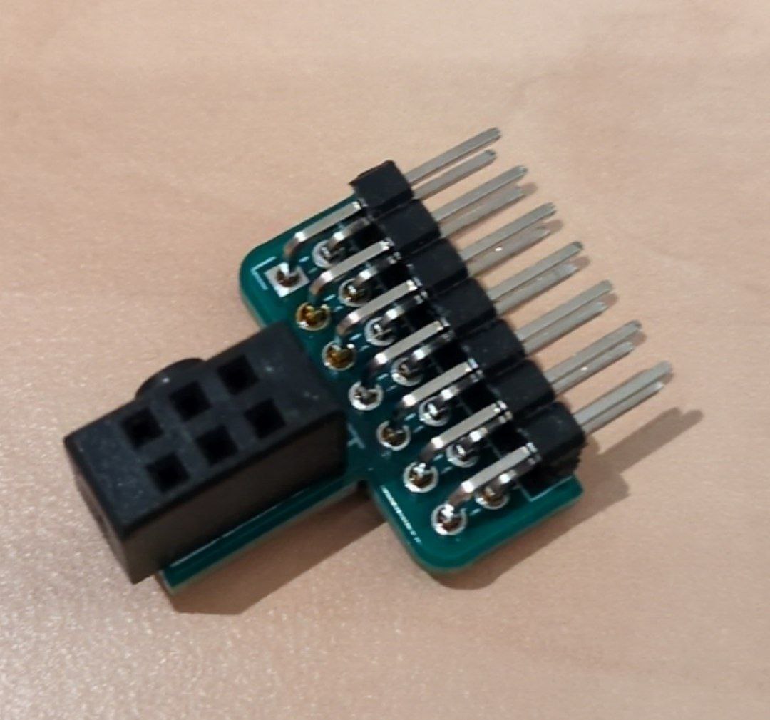
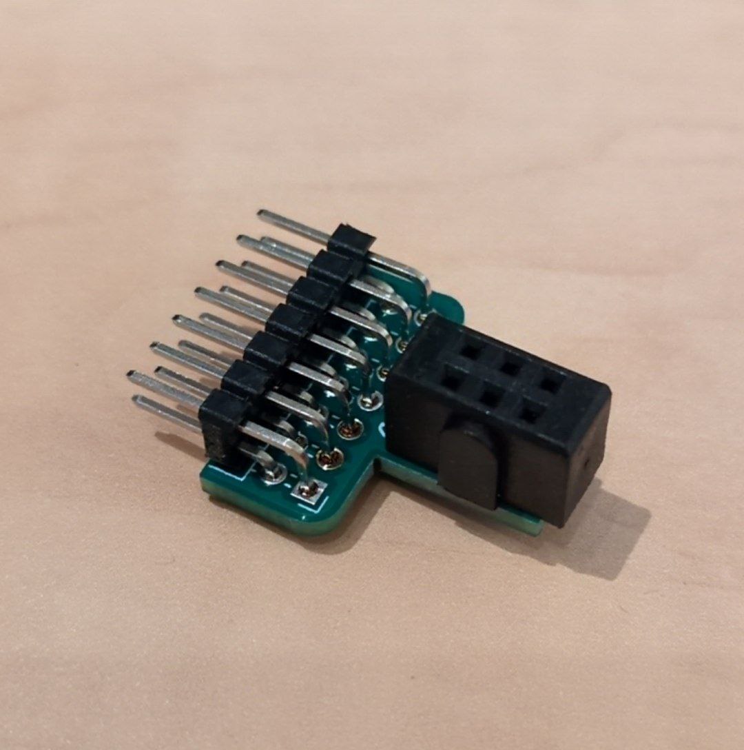
1.1 - SAO adapter
The CATT to SAO adapter is a small adapter board that converts the external add-on port of Tanmatsu into a standard “Simple Add-On” port as found on various event badges.
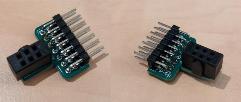
Assembling the adapter
The recommended method for assembling the adapter board is to start with the male pinheader connecting to Tanmatsu as this component is of lower height than the boxed female header for the SAO side. Make sure that the side of the board with the “CATT SAO” text is the side on which you plug in the connectors, assembling the board upside down will not work.
Pin mapping
Pinout
| CATT | SAO | Description |
|---|---|---|
| 1 | ||
| 2 | ||
| 3 | ||
| 4 | ||
| 5 | ||
| 6 | ||
| 7 | ||
| 8 | ||
| 9 | ||
| 10 | ||
| 11 | ||
| 12 | ||
| 13 | ||
| 14 |
Photos
2 - Tanmatsu: internal add-on port
This port is not exposed by default, and a modified back cover needs to be used to make it accessible. For this reason the port is also named the “internal expansion port”.
Pinout
| Pin | Function | Name | GPIO | Description | Notes |
|---|---|---|---|---|---|
| 1 | Power output | VOTG | - | Output from booster DC/DC converter in the PMIC | 5 volt when booster is enabled, +/- VSYS when booster is disabled |
| 2 | USB | HUB_USB1_P | - | Port on USB hub for USB-C port (DP) | Can be used to expose an USB device on the add-on to the PC plugged into the USB-C port |
| 3 | Power output | VBATT | - | Battery voltage (3.0 – 4.2v) | Directly connected to battery connector, always on even when the device is turned off |
| 4 | USB | HUB_USB1_N | - | Port on USB hub for USB-C port (DN) | Can be used to expose an USB device on the add-on to the PC plugged into the USB-C port |
| 5 | Power output | VSYS | - | System voltage (3.0 – 5.0v) | Switched power rail for powering the system, can be powered by battery or USB-C port, off when device is turned off |
| 6 | Power ref. | GND | - | Voltage reference (ground) | |
| 7 | Power ref. | GND | - | Voltage reference (ground) | |
| 8 | Power output | +3.3v | - | Main logic supply rail (3.3v) | |
| 9 | I2C | INT_SCL | 10 | Internal I2C bus, shared with other I2C devices (SCL) | Used to connect I2C devices and an EEPROM for add-on identification |
| 10 | I2C | INT_SDA | 9 | Internal I2C bus, shared with other I2C devices (SDA) | Used to connect I2C devices and an EEPROM for add-on identification |
| 11 | GPIO | E0 | 36 | GPIO | |
| 12 | GPIO | E1 | 0 | GPIO | |
| 13 | GPIO | E2 | 6 | GPIO, also connected to camera GPIO 1 | Shared with camera connector |
| 14 | GPIO | E3 | 46 | GPIO, VSDCARD LDO must be enabled to use this pin | Connected via level shifter, externally these GPIOs operate at 3.3v but the GPIOs are powered by the VSDCARD power domain |
| 15 | GPIO | E4 | 47 | GPIO, VSDCARD LDO must be enabled to use this pin | Connected via level shifter, externally these GPIOs operate at 3.3v but the GPIOs are powered by the VSDCARD power domain |
| 16 | GPIO | E5 | 48 | GPIO, VSDCARD LDO must be enabled to use this pin | Connected via level shifter, externally these GPIOs operate at 3.3v but the GPIOs are powered by the VSDCARD power domain |
| 17 | GPIO | E6 | 45 | GPIO, VSDCARD LDO must be enabled to use this pin | Connected via level shifter, externally these GPIOs operate at 3.3v but the GPIOs are powered by the VSDCARD power domain |
| 18 | GPIO | E7 | 7 | GPIO, in low power domain of P4, has 51k pull-up resistor | Can be used as wakeup pin to wake up the ESP32-P4 from deep sleep |
| 19 | GPIO | E8 | 54 | GPIO | |
| 20 | GPIO | E9 | 49 | GPIO | |
| 21 | GPIO | E10 | 53 | GPIO | |
| 22 | GPIO | EXT_USB_P | 26 | Can be used as GPIO or as USB FS PHY (DP) | The USB PHYs of the P4 can be swapped between the USB serial/jtag and user controlled USB peripheral. If badgelink is used then this PHY exposes the serial/jtag peripheral |
| 23 | GPIO | E11 | 52 | GPIO | |
| 24 | GPIO | EXT_USB_N | 27 | Can be used as GPIO or as USB FS PHY (DN) | The USB PHYs of the P4 can be swapped between the USB serial/jtag and user controlled USB peripheral. If badgelink is used then this PHY exposes the serial/jtag peripheral |
| 25 | GPIO | E12 | 51 | GPIO | |
| 26 | GPIO | P4_TX | 37 | Exposes boot console of P4, can be used as GPIO | Must be low during boot |
| 27 | GPIO | E13 | 50 | GPIO | |
| 28 | GPIO | P4_RX | 38 | Exposes boot console of P4, can be used as GPIO | Must be high during boot |
| 29 | I2S | I2S_MCLK | 30 | Digital audio bus master clock | Reference clock for connected I2S devices |
| 30 | I2S | I2S_LRCK | 31 | Digital audio bus word clock | Word clock (left-right selection) for connected I2S devices |
| 31 | I2S | I2S_DATA | 28 | Digital audio bus data output | Data output from mainboard for connected I2S DACs |
| 32 | I2S | I2S_SCLK | 29 | Digital audio bus sample clock | Sample clock for connected I2S devices |
| 33 | Power output | +3.3v | - | Main logic supply rail (3.3v) | |
| 34 | I3C | I3C_SDA | 33 | I3C bus, shared with QWIIC connector (SDA) | Can also be used as I2C bus |
| 35 | Power ref. | GND | - | Voltage reference (ground) | |
| 36 | I3C | I3C_SCL | 32 | I3C bus, shared with QWIIC connector (SCL) | Can also be used as I2C bus |
Identification EEPROM
Please include a small EEPROM at address 0x50 on your boards, this will allow Tanmatsu to identify which add-on board has been connected.
The format for the content of this EEPROM has yet to be determined, currently the launcher firmware has no support for identifying add-ons.
The format will most likely be based on the format described here.
Usage
We recommend to start with the GPIOs that do not have shared functions. The following GPIOs on the add-on header can be used without limitations:
E0, E1, E7, E8, E9, E10, E11, E12 and E13
If the built-in LDO number 4 of the ESP32-P4 is enabled (this powers up the SD card slot) then the following GPIOs will be available,
a level shifter is included on the main board so these GPIOs are always using 3.3v voltage level regardless of the SD card operating in 3.3 volt or 1.8 volt mode.
E3, E4, E5 and E6
The following pins can also be used if remapped to GPIO, there might be some activity on these pins during startup or while the launcher is running:
EXT_USB_P, EXT_USB_N, P4_TX and P4_RX
The following pins share functions with other peripherals on the main board. Use these with caution:
E2, I2S_MCLK, I2S_LRCK, I2S_DATA, I2S_SCLK, I3C_SDA and I3C_SCL
Using these pins for other purposes than their intended purpose will render either on-board audio, the QWIIC port or the camera port unusable when the add-on board is plugged in.
Limitations & warnings
- Total for all 3.3v outputs must not exceed 1A of current. It is generally adviced to stay well below this figure.
- Do not exceed a current of 1.5A from the battery when the battery is connected to the internal battery connector
- Do not charge the battery via the internal add-on port